Feature first published in the January/February 2022 issue of 3D ADEPT Mag. Interviews, roles and industrial examples reflect that period.
Remember when we told you that post-processing is an umbrella term that covers a variety of stages that 3D printed parts have to undergo before being used for the final purpose? With the goal of providing a thorough understanding of each post-processing task, we have started sharing key insights into issues raised by metal powder removal, the use of furnaces in Additive Manufacturing, or even the Automated Dyeing Process For 3D Printed Parts. In this article, we will have a look at the best practices and tips to know when conducting a surface treatment method in metal 3D printing.
AM enables complex designs, but the resulting geometry and surface condition depend on file preparation, the process and its parameters. Deviations must be assessed against the part’s tolerances.
Several causes may explain that:
- When a curved surface is exported as triangles, tessellation introduces an approximation whose precision depends on the settings. Not all formats and preparation workflows follow exactly the same route.
- Layer-by-layer manufacturing can produce a staircase effect on inclined or curved surfaces. Build orientation and layer thickness affect its extent.
- Geometry, material, process parameters and thermal effects can also influence dimensions and surface condition.
Surface treatment can address appearance, roughness, contact, wear or corrosion requirements. No treatment automatically improves all these properties: it can also alter dimensions or a functional surface and must be qualified for its intended use.
This feature will provide a closer look at surface treatment methods operators can conduct for metal 3D printed parts. To discuss this topic, we have invited key contributors from two companies: Jan Panhuis, Senior technical commercial advisor at Leering Hengelo (Normfinish) as well as Paul Gagorik, Solution Architect and Behrang Poorganji, VP Material Technology from Morf3D.
Normfinish is the Leering Hengelo brand presented in this feature. The company supplies media-blasting equipment for cleaning, deburring, matting, surface preparation and peening.
Morf3D contributes the perspective of an aerospace parts manufacturer. Operations described in the interview include depowdering, non-destructive inspection, thermal treatments, build-plate and support removal, machining, surface treatments, assembly and qualification records. Hot isostatic pressing (HIP), solution treatment, ageing and quenching concern material properties; they are not, in themselves, surface-finishing processes. Gagorik and Poorganji focus here on the latter family.
We also thank parts manufacturer 3DEO, online manufacturing platform Factorem and SPC – Surface Treatment Experts for the resources shared.
Justifying the importance of surface treatment methods
Methods can be grouped by their action on the surface. These families sometimes overlap; this overview does not replace the specifications and standards applicable to each operation.
- Mechanical material removal: sanding, grinding, polishing, lapping and certain media-finishing methods.
- Chemical or electrochemical treatments: pickling, chemical polishing, electropolishing or passivation, with distinct functions.
- Coatings and conversion layers: painting, metallic deposition or anodising, depending on the material and use.
- Controlled plastic deformation of the surface: shot peening, notably to introduce compressive residual stresses.
According to Panhuis, no matter what surface treatment option you choose, the most important issues to address concern the “dimensions of the part, the desired roughness, the optical requirements, the type of treatment (is it a manual or an automatic treatment?)”. Material and any medical function also impose specific requirements. Blasting a titanium part does not establish that a device is ready for use: cleaning, final condition and validation still need consideration. “For some parts again, we need to check the allowed amount of contamination with blasting media”, Panhuis adds.
Gagorik and Poorganji go further as they take into account the complexity of the part, its performance but also all the steps that may influence its final cost. They draw attention on the fact that “the ability to correctly/thoroughly apply a treatment to all intended surfaces, can be impeded by increasing the complexity of part design”. Key contributors in this case, include cleanliness, surface topology, and accessibility. “One important concern is how surface requirements in 3D printed part relates to materials property (For example HCF, LCF, Corrosion) and overall part performance. This is critical as dictates what surface finish treatment and metrics need to be achieved for each part CTQs*. This will eventually drive the cost and viability of AM process”, the experts explain.
CTQ: critical-to-quality characteristics. HCF and LCF refer to high-cycle and low-cycle fatigue, respectively.
A closer look at surface treatment methods
Selection starts with the part’s requirements: material, geometry, accessible surfaces, tolerances and service conditions. These criteria apply to both additive and conventional processes.
“It should be driven greatly by the intended operating environment (assembly/installation, operation/performance, maintenance, decommission) of the part. It should not be driven solely by existing standards, specifications, “best-practices”, etc.. – as all these approaches were created with specific assumptions/conditions that may not apply in all cases. Significant savings (in downstream lead-time and cost) can be realized when taking necessary time to interrogate your application before you design/define. The surface treatment is typically determined by the part CTQs, dimensional requirements, and heavily depends on the AM process (Modality)”, the Morf3D experts lay emphasis on.
Application assessment complements the relevant standards and regulatory requirements; it does not waive compliance with them.
That being said, let’s have a look at some of these methods – irrespective of their main category:
- Sanding. An abrasive removes material and can reduce certain irregularities. Access to recesses and the risk of altering dimensions need assessment.
- Ultrasonic polishing. A vibrating tool works with an abrasive. Frequency, contact and force depend on the system; there is no universal “non-contact at 30 kHz” rule. The tool manufacturer’s instructions are essential.
- Laser polishing. A thin surface layer is remelted to reduce certain irregularities. Fraunhofer ILT describes this principle. Final roughness depends on alloy, initial condition and parameters, with no universal Ra value.

- Chemical polishing and electropolishing. These remove material through controlled dissolution. Electropolishing combines an electrolyte and electric current; it is distinct from passivation. Results depend on material and procedure.
- Barrel finishing. Parts and media move in rotating equipment. A rotary barrel and a centrifugal system are not equivalent: intensity depends on the machine, media and settings, with no guarantee of being gentler than vibratory finishing.
- Shot peening. Controlled impacts cause plastic deformation and compressive residual stresses. The process described by Curtiss-Wright can use metallic, glass or ceramic media; intensity and coverage must be controlled. This is not solidification.
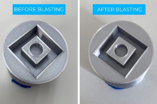
- Bead blasting. This can clean or change surface texture, depending on media and parameters. Access to internal channels is not guaranteed and must be verified; this treatment is not automatically equivalent to qualified shot peening.
- Abrasive blasting. Media and projection energy determine material removal and appearance. Comco presents examples of microblasting printed parts. Fatigue or corrosion benefits are not automatic and require application-specific validation.
- Vibratory finishing. Parts, media and process compounds move in a vibrating container for operations such as deburring, edge rounding and smoothing. The mass-finishing methods described by Rösler must suit part geometry and fragility.
- Metallic plating. A metallic layer can provide particular surface properties. The substrate is not limited to steel and the layer is not necessarily chemically inert. Preparation, adhesion, thickness and service conditions determine the result.
The post-processing sequence must be defined for the required final condition. One operation can alter another’s outcome; cooling and depowdering alone therefore do not determine when finishing should occur. Gagorik and Poorganji emphasise the importance of this planning.
“Surface Preparation processes (including Ultrasonic Cleaning, Abrasive Flow, Electro-polishing, Chemical Milling) typically happen prior to any surface Coatings (including Anodize, Metallic/Ceramic, Paint), and can sometimes be required (as cleaning operations) prior to Heat Treatments and Assembly processes as well. Usually, the surface finishing is coming at the later / final stages of the post processing. However, the sequences of the process is designed in a way to maximize the performance and minimize the cost”, the experts point out.
One key consideration at the heart of surface treatment methods: surface roughness
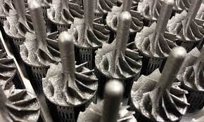
Experts have made it clear that all aspects of the 3D printed part, such as the material, shape, thickness, and weight, its planned use, and the environment in which it will be used, count when it comes to choosing a surface finish option. However, beyond all these aspects, a key emphasis has been made on “the surface roughness problem” of additive manufactured parts.
“Surface roughness is a measure of the variance in a part’s surface topology. Roughness can affect part aesthetics (e.g. shiny or matte) and mechanical behaviour like crack initiation, wear resistance, fatigue life, marine, sealing, bearing, and fluid dynamics. The rougher the surfaces in an integrated dynamic machine, the less quietly, efficiently, and safely it will operate. Reducing roughness, or friction, is critical in mechanical parts like pistons, bearings, and seal surfaces where too much contact between moving surfaces can lead to rapid wear and tear. Specifications may differ by case, but the smoothness required of an end-use part can be an important factor in costing it. Surface roughness analysis includes the use of parameters to inspect and determine whether the part manufactured meets quality control standards. This helps manufacturers and designers quantify the roughness of the surface finish they select” Matt Sand, Founder & CEO at 3DEO, comments.
In metrology, Ra is an arithmetic mean profile deviation, not a variance or a direct friction measurement. Different profiles can share the same value. NIST’s calibration work highlights measurement conditions. Direction, filtering and selected parameters should be specified for the surface’s function; “smoother” does not always mean “more suitable”.
Initial surface condition varies with the AM process and its parameters. A treatment can be matched to a particular process, but suitability must be demonstrated for the material, geometry and part requirements rather than inferred from the process name alone.
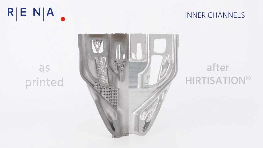
For Morf3D, it is essential to understand the starting conditions for acceptable application of the surface treatment needed for the given material and part application, and then determine what manufacturing processes are necessary to get you there. Taking the example of their in-house capabilities, Gagorik and Poorganji note that the surface treatments they are using today, are the advanced/developed version of the existing processes for conventional processes which are modified or geared towards the needs of 3D printed parts. For example, access to internal channels which are rougher than a machined channel, or chemical-mechanical polishing of a rotating component surface.
Lastly, the reasons for using a surface finish apply both to 3D printed parts and parts manufactured with traditional processes. Since different finishing options come with different costs, responsibility, as per the words of Morf3D’s experts, lies not on the technology used to manufacture, but on informed design and manufacturing teams in collaborating to make the best decisions on what to use.
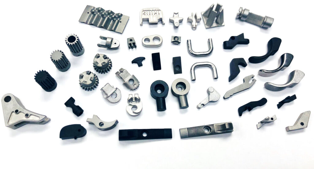
Featured image: metal 3D-printed parts. Image: 3DEO.
THE 3D ADEPT WEEKLY NEWSLETTER
The industry moves fast. Stay ahead.
Every week, the latest additive manufacturing news, in-depth features and real-world applications, straight to your inbox. Plus, be the first to know when a new issue of 3D ADEPT Mag is out.
Free · One email a week · Unsubscribe anytime
Clicking loads our email provider’s sign-up form, including its analytics and Google’s anti-bot protection. You’re only subscribed if you complete the sign-up. Read our privacy policy.