

There are two types of people working with 3D printed parts: those who know how to deal with support structures and those who don’t. Last year at Formnext, while walking across the aisles, I saw a couple of parts that were built without support structures and a couple of them where they seem to be necessary. It got me thinking: should the operator build a “support structures” strategy?
Strategy might be a strong word but in Additive Manufacturing, I came to realize that despite this advocated “out of the box” philosophy, everything has to be thought twice including the things you least expect.
In this case, the words “support structures” themselves are quite explicit. Described by many in the industry as a “necessary evil”, there are structures that support (pun intended) your component during the AM process. The goal? Ensuring that the part comes out of the 3D printer without any deformation caused by sagging. Nevertheless, the upfront thinking process is worth having once you realize that they might actually affect the price of your part.
The article below aims to discuss:
- What AM processes may lead to the formation of support structures (SS) – in case you’re new to AM – and most importantly, why do we need them?
- What is that cost consideration?
- And how should we approach a “support structures” strategy?
What AM processes may lead to the formation of support structures (SS) & why do we need them?
First and foremost, “support structures are needed to connect the parts to the build plate. Without any connection, the recoater would push the molten material to another position. In addition, supports are needed to absorb material tensions that occur during solidification of the molten material. Furthermore, support structures dissipate heat from the part to the baseplate and thus prevent overheating, Dominik Maurer, TRUMPF Additive Manufacturing, Application and Process Development, states from the outset.
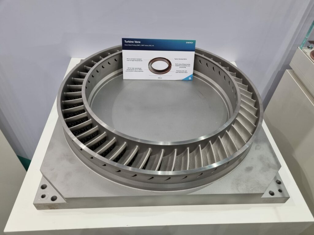
Images taken on 3D Systems’ booth at Formnext 2022
Anyone with a slight experience in FDM 3D printing may have already come across an occasion where they have made use of SS. Since the technology process works by depositing layer over layer of filament, each new layer must be supported by the layer beneath it. It’s physics!
That “fixation” reason also applies to SLA and other resin-based technologies such as DLP and LCD.
Surprisingly, while SS are not required for SLS technology, they are required for DMLS (Direct Metal Laser Sintering). Furthermore, given the high temperatures in the build volume, they also ensure heat is evenly dissipated.
Needless to say, the formation of SS implies certain specifications that are peculiar to each technology:
“Support structures are needed for different reasons depending on the technology, and in some instances are not needed at all. For example in Selective Laser Sintering (SLS) there are no support structures, parts float free in adjacent build powder allowing you to build complex parts with little geometric compromise.
In the case of Stereolithography (SLA), i.e. real vat-based top-down no-membrane, very minimal supports are needed as the build process is largely buoyant, and the supports you do use are very fine point, material efficient, and easy to remove. Generally, they are required to initiate, stabilize and then precisely fixture emergent cross-sections. With SLA you can get away with very shallow surfaces and large self-supporting spans.
When a membrane is introduced as we see in the case of DLP, LCD, and some laser-based systems the supports become more rugged and robust, depending on the type of membrane as well as the nature of the geometry.
With FDM and/or general plastic extrusion systems, supports are pretty extensive as you are building in air and the effects of gravity as well as process tension from the cooling shapes drive the need for extensive anchors. That being said, there are tricks deployed here ranging from design modification to special process settings to interact with the interfaces to reduce the density as well as improve the removal process.
In the case of Direct Metal Printing (DMP), supports are actually multi-functional. Not only are they generally needed to initiate down-hanging geometry, they actually serve two functions both as fixtures to hold down cross-sections from the stress accumulation during the build process to transferring heat out of the geometry during building.
Recently, as engineers better understand the complex physics involved in melting and re-solidifying powdered metals we have seen remarkable step changes in support reduction, to the point now where it’s often possible to get rid of the bulk of them. This has a huge impact on material consumption, build times, and downstream labor. But the biggest impact is on design. “The best support is no support” philosophy – enabled by advanced process development and vector level control – is expanding the design space. Design is a fundamental value proposition of AM,”
Patrick Dunne, Vice President, Application Integration Group, 3D Systems, states.
What is that cost consideration?
 We are often told that post-processing is the manufacturing step that increases the final cost of the 3D printed part. By saying that, it might be easy to overlook the other (minor considerations) that keep increasing the cost in the end.
Take FDM for instance, since SS require additional printing material, this somehow increases the production cost within this process. Not to mention that whoever says SS means some additional work at the post-processing level, and this – regardless of the AM process used, which means more cost in the end.
On another note, as we advocate more and more the need for “greener” manufacturing processes, let us remind that SS also somehow means more “material waste”. “Some materials require more support than other materials due to differences in the internal stresses of the material when solidifying. For example, many aluminum alloys require rather few supports compared to stress-intense materials like titanium alloys,” Maurer says.
The problem is, since the manufacturing process is the primary driver of SS, engineers are left with one main option to avoid or minimize their formation: improve their part design. An idea that Dunne confirms: “[the] presence [of SS] is driven by the combination of hardware and manufacturing process, materials, part design, and of course, build orientation. Combining DfAM with optimal orientation and fine process control capabilities can reduce them massively – in some instances to zero!”
The “support structures” strategy
Since it all begins in software, adopting an SS strategy through DfAM means that the engineer should integrate the SS into the design in a way that fulfil multiple functions.
“Ideally, that is done by designing the parts without any critical overhanging surfaces that have to be supported. Conventionally, all surfaces with an overhanging angle of lower than 45 ° to the baseplate had to be supported. Due to intelligent process parameters for the overhanging areas (the so-called “downskin parameters”) it is now possible to print overhanging angles to around 25 ° without any support structures. With special adjustments of the downskin parameters it is sometimes even possible to print angles down to 10 ° without any support structures. As the surface quality of these low angle surfaces is comparably bad and the special downskin parameters often go in line with additional print time, surfaces of lower than 25 ° are still to be avoided in the part design if possible,” Maurer explains.
By taking the specific example of LPBF where the need for support structures depends in particular on the geometry of the part and the print material, he specifically adds:
“Generally speaking, the design of the parts should be suitable for the LPBF Process. There are a lot of guidelines like minimal wall thicknesses, maximum hole diameters or the lowest support-free angle. At TRUMPF, we offer design for LPBF trainings to internal and external design engineers to enable them screening potential LPBF parts and often redesigning the parts suitable for the LPBF Process.
In most cases, part design is done with conventional CAD Software. There are many useful features for the designers to optimize their parts for LPBF and to reduce support structures. But these features do not replace the general understanding of the design guidelines for LPBF of the design engineer.”
This seems to be a lot of constraints for a technology that should allow “design freedom”. If sometimes, holistic experience teaches the best lessons, here are a couple of ideas that we would like you to consider:
- Use a software solution that allows for the control of supports in your 3D printed parts
- Ensure control over build parameters in the area of the part’s overhang feature
- According to 3D Systems’ expert, simple tricks like self-propagating features that don’t need supports or even embracing them and making supports permanent and integrated can help a lot. By making the supports part of the design and left in place you remove that labor required downstream
- Otherwise, in-situ monitoring could be another option. By using a contactless recoating system for instance, the engineer can remove the need for supports
- Something interesting we saw at Formnext 2022 was a solution brought by machine manufacturer Duplex. By 3D printing from above the part and below at the same time, the lower 3D printing head becomes an answer to support since it essentially is the SS. As you may see in the video, the nozzle itself supports overhanging features as they are being fabricated.
- Lastly, another recent example that popped up on the market focuses on the thermal management of the melt pool. With their Free Float solution, for example, SLM Solutions gives options to users to choose between profiles depending on the part quality and support elimination desired.
Concluding thoughts
SS are definitely an interesting area of development for AM as new solutions are being developed to achieve “no support” manufacturing. While they may affect the design, the material and even the post-processing decisions in AM, they reinforce the idea that there is no “one size fits all” solution in AM.
This dossier has first been published in the 2023 July/August edition of 3D ADEPT Mag.


