

In a previous dossier dedicated to the use of furnaces in additive manufacturing, we found out that the reasons that may help catalogue the type of furnaces manufacturers will use, are often dependent on the process the part will undergo: sintering (and often debinding) on the one hand, and heat treatment on the other hand. Here is the thing, heat treatment is a bottleneck that is quite underestimated… yet a thorough understanding and handling of this process can help manufacturers to avoid a wide range of unexpected challenges.
When looking at the various post-processing steps that can be carried out in an additive manufacturing process, it’s easy to understand why powder removal is given top priority. Everything surrounding this process is relatively “new”, whereas for heat treatment, operators easily see some similarities between the steps they need to take, to heat treat their 3D printed parts and the steps to follow when the part has been manufactured via a traditional route. That’s probably where the trap is. They only see “similarities”.
This article aims to highlight the main differences between heat treatment performed for AM and heat treatment performed for conventional manufacturing processes. A specific emphasis will be laid on typical heat treatment steps & considerations to take into account for L-PBF, EB-PBF and Binder jetting.
Heat Treatment: AM vs Traditional manufacturing processes.
As a reminder, heat treatment consists in heating material to a specific temperature and then cooling it to enhance its mechanical properties. In theory, the process involves three different stages**: heating, soaking, and cooling. In practice, the grades and cycles are different, and sometimes, there might be slight variations that occur depending on the metal AM process utilized. Interestingly, these cycles are often referred to as heat treat processes or techniques. Four of them** stand out (from the crowd): annealing, normalizing, quenching, and tempering.

“The differences between heat treat cycles are based upon and driven by chemistry [understand, chemistry of the material processed]. Chemistry dictates what heat treatment step you need to take to achieve your desired properties. That’s the reason why, for instance, different alloys will require different heat treat cycles. Even within the same alloy, you might have different levels of heat treatment as well. In this case again, your chemistry will dictate what’s going to happen if you heat the part in a certain way” Anthony Mott, Global Additive Manufacturing Leader at Wabtec, told 3D ADEPT Media.
Acknowledged for the fabrication of products for locomotives, freight cars and passenger transit vehicles, Wabtec made a real splash in the AM industry last year, when it became the anchor tenant of Neighborhood 91, an additive manufacturing supply chain hub located on the 195-acre airport campus. Mott and his team are on a mission to integrate AM within the company. To do so, they work with other engineers across the company to understand the applications and explore where it makes sense to apply AM.
Reasons to perform a heat treatment process therefore vary from one application to another and the goal to achieve. In one case, the objective might be to soften the metal while in another one, the objective might be to increase hardness or develop certain mechanical properties to the metal or alloy used.
When one tries to compare heat treatment performed for AM & heat treatment performed for traditional manufacturing processes, there “is limited to no differences between these two types of manufacturing processes. If you are using the same exact chemistry on the traditional side for instance, the material is the same and it’s what really dictates your heat treatment profile. With AM, the only change is that you may have a more narrowed temperature profile. For example, you might run a high-performance nickel alloy processed by traditional processes from 1750 to 1950 while with additive, you’ll run it from 1850 to 1875° – That’s why I talk about a much narrower window on the same profile. The reasons why you may have some deviations in temperature is because with AM, we have a melt pool that melts your material and then rapidly cools. You have much smaller microstructures, much smaller green structures vs a cast part that has very large melted cool areas. That’s why you need narrow process profiles. This will help you ensure to get consistent properties out of this thermochemical treatment”, Mott told 3D ADEPT Media.
Mott’s statement highlights three essential considerations to take into account when performing heat treatment: temperature, materials and microstructure challenges.
Heat treatment by nature is about control, control of the heating temperatures, control of the cooling rates, and the quenching types that are used to land on the desired properties.
In the same vein, it’s normal to witness some slight differences in the reaction of materials that are processed via traditional processes versus when processed with AM. “It’s difficult to 3D print pieces using materials containing high amounts of carbon, such as many steels. Carbon leads to issues in the microscopic resolidification that occurs in the AM process. It can affect expansion, contraction, shrinkage, and localized stresses, causing parts 3D printed with high carbon material to have cracking issues once completed. While carbon greatly complicates 3D printing, it is essential in many heat treatment processes”, an expert at Paulo notes. – Paulo is an organization that has dedicated its core business to address thermal processing challenges.
Besides materials, one thing that is often difficult to avoid in heat treatment is distortion in 3D printed parts. That deflection of the component from the shape created by the AM process can be caused by a variety of loads placed on or inside the part by the AM process or the surrounding environment. For some experts, the more complex the part is, the more it might deliver tight tolerances that one does not always have with conventional manufacturing processes such as machining, and the greater the chances are to face some distortion. On this specific point, experts have various opinions to mitigate the risks of distortion:
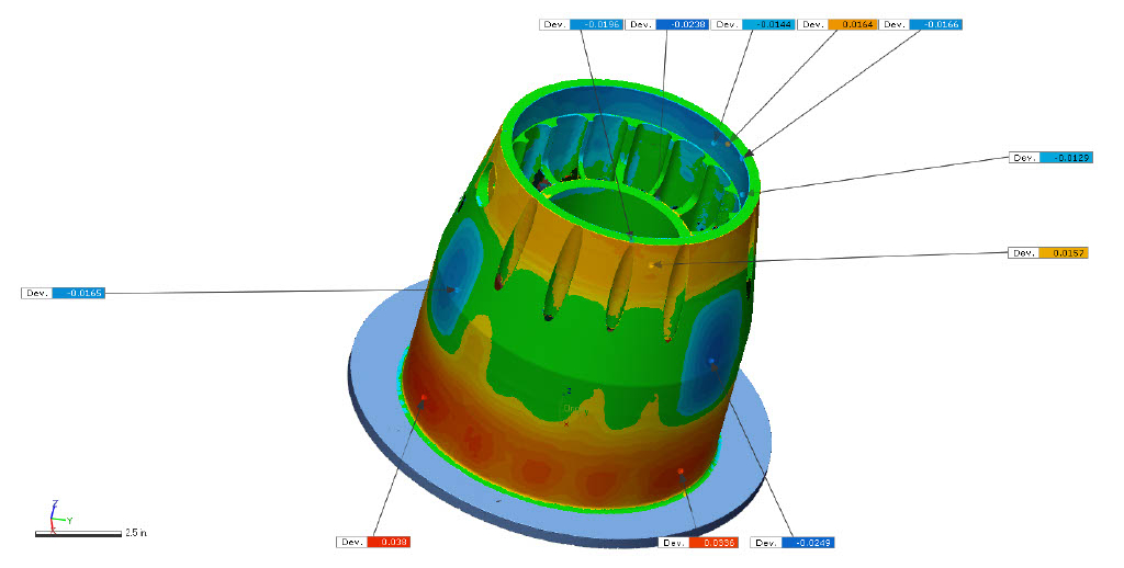
For the team at Paulo, “the risks of distortion can be mitigated by precise adjustments to the part’s initial design to yield a geometry in the treated piece that will fit in the application.” For others, one can heat treat the parts together with the build platform to avoid major distortion. Another interesting idea comes from metal additive manufacturing service provider and CNC machine shop Wagner Machine that 3D scans practically every one of its 3D printed parts after it returns from heat treating. The idea of the engineering team at Wagner is to grab every possible information that can help them understand the effect of heat treat on 3D printed parts, in order to better predict heat-treating-induced distortion.
To illustrate this point, the company shared the image of a microturbine generator housing they created using aluminum alloy F357 on an LPBF 3D printer. The part is about 23 cm in diameter by 23 cm tall (9 inches x 9 inches) and it is made with large open spaces inside its form through which fuel flows to cool the part. After careful analysis, the team admitted that these unsupported openings increased the margin for potential distortion.
However, while most of the time, the main goal of heat treatment is to stabilize the metallic microstructure and balance material properties, one tends to realize that these microstructure challenges may vary from one metal 3D printing process to another.
Considerations to take into account for L-PBF, EB-PBF and Binder jetting
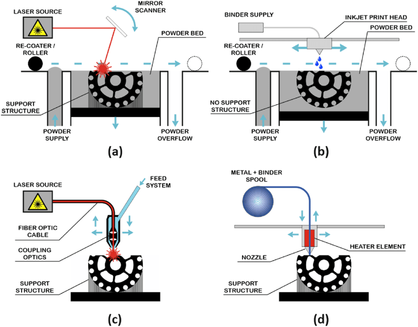
Amid the range of metal AM processes that are commercialized on the market, there is a great chance that you have already heard or deal with laser powder-bed fusion (L-PBF), electron beam powder-bed fusion (EB-PBF) and binder jetting. When your part is manufactured using one of these processes, it is almost always advisable to apply a heat treatment at the post-processing stage. However, applications of this process may come with some differences. Wabtec’s Global Additive Manufacturing Leader highlights the most important ones:
“There are some changes that do happen across the three AM processes. For example, in L-PBF, the build temperature is anywhere from 50°C to 200°C. This creates very high stresses in the part, which leads to the use of a stress-relief thermos treatment followed by a full heat treatment. For binder jetting, you need to remove the binder on the part, that’s why you will need to conduct a debinding stage before a sintering process. Only after this, you could potentially jump in the same heat treatment that you would use in L-PBF. For Electron Beam Melting, the temperature you will deal with, could range from 600 to 1000°C. In this process, when you are printing, even though you are putting a lot of stress on your part, you are running a stress profile, so you won’t necessarily need a stress-relief treatment here”.
By taking the example of laser powder bed fusion (LPBF), the expert at Paulo lays emphasis on a phenomenon called microsegregation, which is the result of the solidification and resolidification of each layer during the printing process.
“In this condition, the AM process itself creates a series of microscopic melt pools (essentially weld pools) throughout the part’s interior structure. Although this can be advantageous by keeping the part’s microstructure very fine, those microscopic melt pools throughout can present segregation issues within the material, with particles separating into distinct zones and affecting the part’s overall structure. This phenomenon can actually work in your favor, since homogenization of the microstructure can happen more rapidly in some AM parts, which reduces hold times during heat treatment.”
The table below summarizes what characterizes heat treatment for each of these metal AM processes:
| Metal AM processes | Laser powder-bed fusion (L-PBF) | Electron beam powder-bed fusion (EB-PBF) | Binder jetting (BJ) |
| Description | This process uses a laser to sinter or fuse atomized powder particles together. Like most additive processes, it is performed one layer at a time until the part is completed. | In this powder bed fusion method, an electron beam is used to melt and fuse material powder together. | In Binder Jetting, a binder is selectively deposited onto a powder bed, bonding these areas together to form a solid part one layer at a time. |
| Type(s) of heat treat process you are likely to perform: | With the rapid melting and cooling of each layer, residual stresses are created in the fabricated components. This means that a stress-relief cycle will need to be performed to minimize distortion.
Depending on the alloy used, and the density to achieve, a HIP (Hot Isostatic Press) treatment might be conducted. |
In this process, the stress relief treatments are not necessary given the hot powder bed process of the technology.
Depending on the alloy used, and the density to achieve, a HIP (Hot Isostatic Press) treatment might be conducted. |
Sintering is required in this process in order to achieve the desired density of the part. (Prior to this stage, there is a debinding stage that needs to be performed). |
With all these considerations, how do you verify if a heat-treat cycle was run successfully?
Anthony Mott shares three tips that can help operators verify if they have successfully performed their heat treat cycles:
- Thermocouples can be attached to the thickest areas in order to ensure that the process is conducted under the desired temperature.
- Operators can also use a “sacrificial coupon” that they will print with the part. You print a cylinder with a hole, and you put a thermocouple rate inside that hole. It will act as a representation of what your part will go through when temperature variation will occur.
- And the last one that’s most typically done is to print test coupons for tensile or density, break them or analyze them to ensure that you are achieving the desired properties in the right area of your part.
What now?
Despite the advancements and precautions one can take during the manufacturing process, it is sometimes challenging to address the mechanical properties variability that occurs when the manufactured part is subjected to different heat treatments and process parameters. The truth is, even if the manufacturing technologies used are performant, the result of each fabrication is greatly influenced by the application and the product reliability. We may not be at the end of the “what ifs” that govern the heat treat cycles and processes when they are combined with AM, but by sharing their holistic experiences, users can learn from the road of success or failures of each other.
Notes to the readers:
This dossier has first been published in the July/August edition of 3D ADEPT Mag.
Here are a few explanations on the main terms used in this article.
Heat treatment involves three different stages**: heating, soaking, and cooling.
During the heating stage, the foremost aim is to make sure that the metal heats uniformly. The purpose of the soaking stage is to keep the metal at the appropriate temperature until the desired internal structure takes shape. In the cooling stage, you’ll want to cool metal back to room temperature, but there are different ways to do this depending on the type of metal.
(Descriptions shared by Kloeckner Metals).
Four heat treatment processes have been mentioned in the article**: annealing, normalizing, quenching, and tempering.
Annealing is a heat treatment process used to modify the microstructure of a metal to improve its ductility while reducing internal stress and overall hardness.
Hardening heat treatments are used to enhance the hardness of the metal’s surface through heating and rapid cooling. The material is heated in a hardening furnace to a temperature that transforms its internal structure without melting it.
Quenching refers specifically to heat treatments that rely on rapid cooling of the metal to achieve the desired physical or mechanical properties. Heated materials are often cooled in oil, but can also be quenched using air, water, and brine, depending on the material and desired qualities.
Tempering is a low temperature heat treatment process normally performed after a hardening process in order to reach a desired hardness/toughness ratio.
(Descriptions shared by S.M. Engineering & Heat Treating). Remember, you can post job opportunities in the AM Industry on 3D ADEPT Media free of charge or look for a job via our job board. Make sure to follow us on our social networks and subscribe to our weekly newsletter : Facebook, Twitter, LinkedIn & Instagram ! If you want to be featured in the next issue of our digital magazine or if you hear a story that needs to be heard, make sure to send it to contact@3dadept.com


