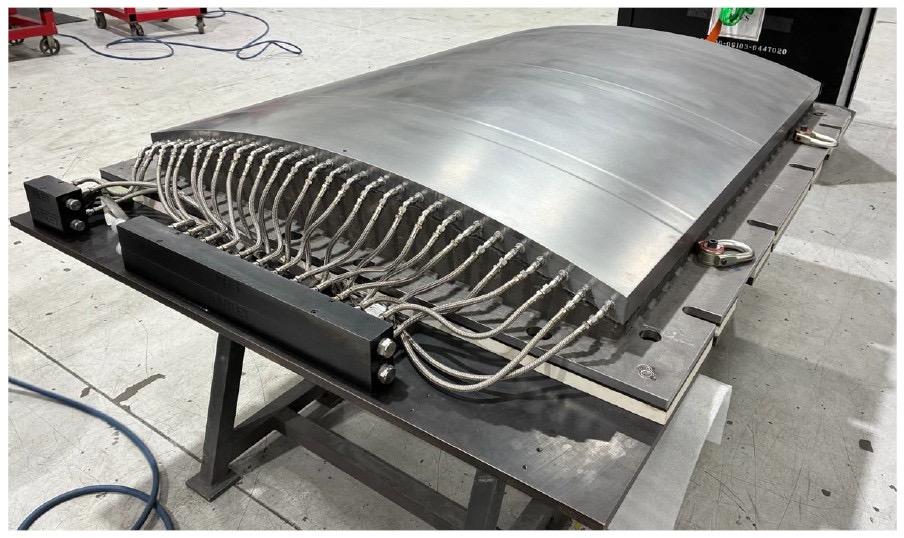
To contribute to NASA’s Hi-Rate Composite Aircraft Manufacturing (HiCAM) project, a joint team from ORNL and Boeing produce a massive Stamp Form Die (SFD) using WAAM.
Produced over 8 weeks, the SFD of 6 feet tall, 4 feet wide and nearly 2 tons, is a punch press used to cut or shape materials.
“NASA and its industry partners are working to increase the production rate of composite aircraft to meet the growing demand for air travel and to reduce aircraft weight, which improves fuel efficiency, lowering costs for aircraft operators,” said Richard Young, NASA HiCAM project manager. “Doing so is essential to maintaining U.S. competitive advantage in the commercial aircraft industry.”
Challenges encountered when making the mold
Thermoplastic aircraft doors are made by stamping hot plastic between two SFD metal molds. Think of the molds as slices of bread for a sandwich, with a sheet of hot plastic as the filling.
Normally, these molds are made through traditional metalworking such as machining, casting, forging, and drilling. Researchers at Boeing and DOE’s Manufacturing Demonstration Facility (MDF) at ORNL wanted to see whether it would be faster, less costly, and easier to 3D print a thermally controlled SFD mold instead.
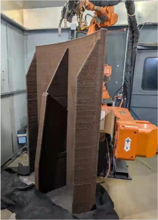
“Boeing wanted to explore the possibility of using wire-arc additive manufacturing (WAAM),” said William Carter, ORNL robotics engineer at the MDF. “They worked with us to evaluate the issues in making the mold.”
This project relied on ORNL engineering expertise in WAAM processes and residual stress simulation, using ORNL’s Arc-1 system. Arc-1 has a robotic arm and a welding torch to melt wire and build metal parts layer by layer.
Unlike most WAAM systems, Arc-1 can print with more than one kind of metal, feeding in multiple wires at the same time. This increases manufacturing versatility, broadens the range of printable geometries, and allows multiple metals to be combined with greater design flexibility for tailored performance.
The Boeing SFD mold leverages mild steel in the structural regions for strength and stiffness, while stainless steel is deposited at the mold surface to provide corrosion resistance, dimensional stability, and a durable working interface.
Such molds usually have long, straight holes drilled into them to create channels that will carry heating and cooling fluids. With 3D printing, engineers were able to instead build in curving channels that closely follow the shape of the mold. This helps heat and cool the part more efficiently and improves mold performance.
One major challenge to 3D printing the mold was warping. As the deposited metal cooled, inherent residual stresses caused twisting and dimensional drift. To minimize this, the team added temporary ribs to the back of the mold and used computer simulations to refine the design and compensate for this warping during the printing process. After 32 simulation iterations, they produced a mold that was within a few millimeters of the intended shape.
Once the mold was successfully printed, it was sent to Baker Industries in Michigan to be annealed to remove internal stress. The support ribs were then cut away. Baker Industries completed all remaining fabrication operations to finish the SFD to achieve all Boeing requirements.
While not all parts of the final tool were 3D printed, the technology developed within this project can be replicated for similar tool types.
*We curate insights that matter to help you grow in your AM journey. Receive them once a week, straight to your inbox. Subscribe to our weekly newsletter.