

With a first patent granted in the 1920s, Wire-Arc Additive Manufacturing, short for WAAM, is certainly one of the oldest AM processes that exist, yet the technology is the least highlighted in the range of recognized AM processes. The reason for this slow adoption at the industrial level may lie in the gap that still needs to be fulfilled in the supply-chain.
Driven by the demand for increased manufacturing efficiency of engineering structures, WAAM which is also known as directed energy deposition-arc (DED-arc), can basically be seen as the integration of an “additive” principle in the wire-arc welding process. According to manufacturers, given the fact that in a welding process, heat energy is used to fuse the molten metallic pools one upon another, the transformation of the process into an additive one was quite understandable. From a technological standpoint, the additive process can deliver high deposition rate of the metallic feedstock in the form of a wire filament, the same as with the conventional welding process. This might explain why first manufacturers of WAAM systems have a strong expertise in the welding industry.
According to Wim Verlinde, Welding Consultant & Engineer atthe Belgian Welding Institute (BWI), other reasons & questions may explain this influence of WAAM in the welding industry: “There are still a limited number of conventional processes for the manufacturing of big parts. Castings are one of these processes but they still require a number of developments such as moulds; and it becomes challenging to make big parts for small series, which in the end might be extremely costly. Another reason is that WAAM can serve a lot of other applications such as repair parts achieved by Guaranteed, spare parts on demand, prototyping, etc.”
Two years ago for instance, the BWI team started a research project (funded by VLAIO – Agentschap Innoveren en Ondernemen – Vlaanderen) when realizing that a lot of robots were shipped to their facilities and remained unused during night or weekend. Verlinde explained that their team came to ask themselves, if they could turn a normal traditional welding robot into a 3D printing robot.
According to the welding consultant, the disruptive impact of WAAM on the welding industry may lie in the fact that the process requires a specific material in different locations of the 3D printed part to achieve for instance fatigue, corrosion, or high stresses. In these cases, the part is built in specific areas with specific materials, or the manufacturing process may require the use of two wires that are mixed in-situ and composed together to achieve a specific goal. (According to the expert, such production scenarios are quite complex as they may lead to some metallurgical issues).
Although it is acknowledged for the large-scale manufacturing industry, WAAM does come with a number of constraints at the manufacturing level. The present dossier aims to:
- Help professionals understand how the WAAM process works;
- Shed light on the different challenges engineers often encounter when manufacturing with WAAM and shed light on the potential solutions that could be used to overcome them. This includes revealing the gap in the supply chain we mentioned above;
- Share some examples of applications & a few WAAM-dedicated solutions available on the market.
WAAM: processes & capabilities
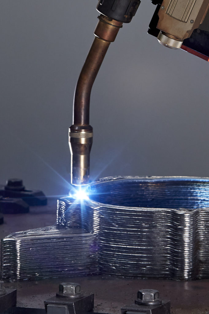
Simply put, in a WAAM process, an electric arc is used as a primary source of the heat to achieve near net shape preforms without the need for complex tooling, moulds or dies. Just like there are several types of metal AM processes, one can identify various sub-categories of WAAM processes.
According to Mark Douglass, Business Development Manager at Lincoln Electric Additive Solutions, those sub-categories are basedon the different arc welding processes:
- “Gas metal arc welding (GMAW) or as is often categorized in Europe “MIG/MAG”; this is the process most often referred to and the one Lincoln employs;
- Plasma arc welding (PAW), which is the one Cranfield University popularized; Gas tungsten arc welding (GTAW) [also known as Tungsten Inert Gas (TIG) welding]”.
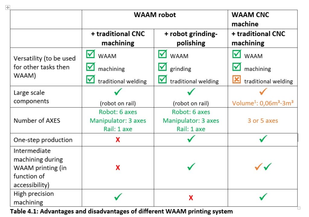
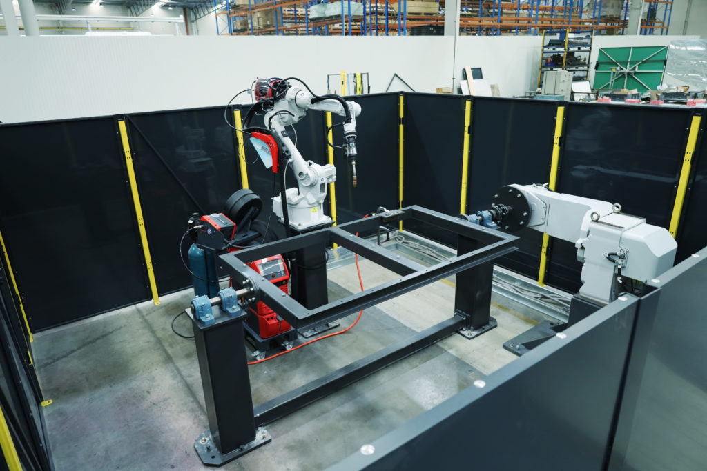
However, as far as the equipment itself is concerned, WAAM systems’ developments vary from one manufacturer to another (as we will see at the end of this dossier) but most of the machines fall into either robotic or machine tool-based. “Some manufacturers start from a CNC machine and turn a CNC machine into a weld printer, and then, they do the machining and the printing within the single platform. Machine manufacturer GEFERTEC for instance, develops its AM machines based on this principle”, Verlinde notes. Furthermore, as he explained earlier, it is possible to combine any three-axis manipulator with a six-axis robot arm and an arc welding power source to develop a basic WAAM system. The robot can be combined with a grinding robot (in one platform) or with a traditional CNC for surface finishing.
No matter how they are built, these machines should be backed by strong CAD/CAM software.
The software perspective
The fabrication process with WAAM starts with a CAM software that helps to generate the toolpath and the welding parameters for the gantry table; then one can control the start/stop points of welding and determine the feed rate of metallic wire filament. As seen in any additive process, the software should be capable to convert the CAD model to a printable code by following the slicing principle. Once the process has started, the welding torch moves in a given direction on the build plate and triggers the wire feeder to deposit the material in the path.
Software tools and systems play an important role in the process preparation. Nowadays, it is possible to divide the existing software for WAAM in two main categories: stand-alone applications and plug-ins that are integrated within existing CAD/CAM software. Plug-ins for WAAM are developed and integrated in a number of CAD/CAM software tools. The main advantage is the possibility to prepare both WAAM and machining steps within a single software platform. The functionality, compared to stand-alone applications, is sometimes limited: mainly in the variety of deposition path strategies, control and setting of the welding parameters, etc…
| Plug-ins (= based on CNC CAM) | Stand-alone (= WAAM specific) |
| Sprutcam robot PowerMill (Autodesk) Robotmaster Hypermill (Dassault Sytems) Siemens NXEureka | Metal XL (MX3D) Factory OS (OQTON) WAAMMat (Cranfield University) |
The Belgian Welding Institute (BWI), VIVES and KULeuven are independent research institutes. Any supplier of CAM WAAM software can be added to this table.
When making a choice, the following software features must be evaluated depending on the application, complexity, shape, etc.:
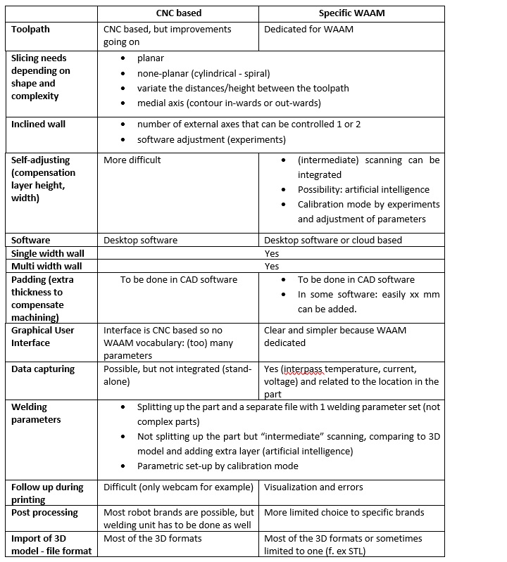
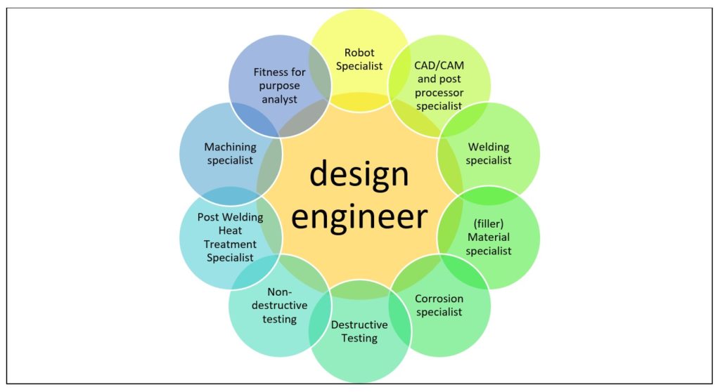
For Verlinde, “the design engineer has a major task here. Unlike other industries like steel constructions or pressure vessels where everything is ruled by (harmonized) standards for the design engineer, here, the design engineer has to decide what the materials’ characteristics are, what potential defects may occur, what kind of finishing is required – since the finishing depends on the application. Unfortunately, he is still limited in his work by standards. For some applications for instance, which have stringent regulations, he does not have the freedom to decide how he will build the part.” The design engineer might require a skilled multi-disciplinary team to decide on all of the topics depending on the complexity and the risks of the part.
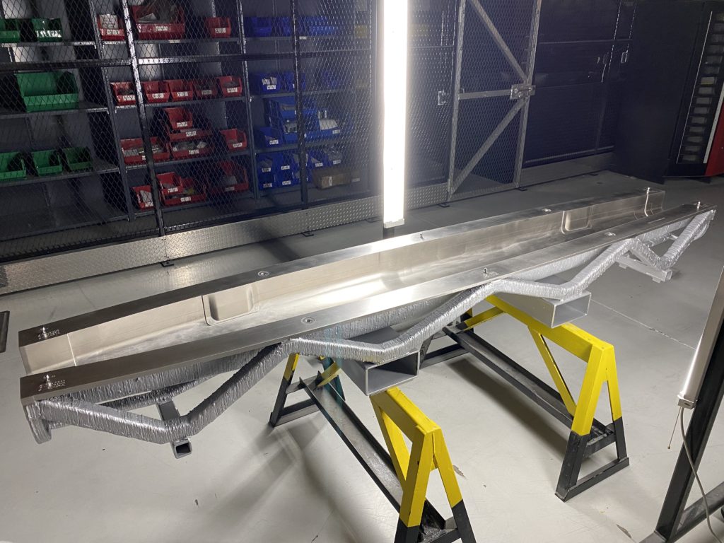
In other terms, designing for WAAM means pinpointing all workpiece geometries that are most suitable for the final real-world applications. In the aerospace industry for instance, new lightweight stiffeners are used to meet specific mechanical constraints.
In the same vein, since the WAAM process delivers high deposition rates, the design engineer should take into account the fact that the large heat input of these processes may also lead to significant residual stresses and distortions.
In such cases, “pre-heating may be used to control distortion. It is possible to model distortion and compensate in the tool path based on the prediction, however I do not believe effective tools have been developed yet. Otherwise experience can help greatly in managing distortion”, Douglass observes.
The fact is that these issues can badly impact the accuracy of the final shape of the parts and their mechanical performance. Therefore, it is important to take the thermo-mechanical behaviour of the WAAM process into consideration during the design stage.
The materials perspective
For each type of power source available, the material in use can drive the given arc deposition process. For instance, titanium alloys are widely processed with gas tungsten arc welding or plasma transferred arc while most materials are deposited with MIG/MAG equipment. In a general, all materials available as a welding wire be used for the production of parts via WAAM although, “certain precautions such as pre-heat may still be necessary”, according to Douglass.
While he agrees with this generalisation, Verlinde nevertheless nuances his answer:
“Most materials are suitable for printing because we weld them but it all depends on what you expect in the end on material characteristics and weld imperfections. Some materials like aluminium and titanium are more challenging and used in critical high-end applications but they enable shorter production time. The problem of most companies on the market, is that they think that WAAM is already at the same place that powder-bed fusion but this is not yet the case. However, it is clear that on many levels (software, machining, research …) great progress has been made since we have started the project”. On the other hand, gas tungsten arc welding can process a wide range of materials including carbon and low alloy steels, stainless steel, nickel-based alloys, titanium alloys and aluminium alloys.
Douglass also raised our attention on the fact that comparisons between 3D printed parts produced via WAAM and parts produced with cast or wrought material are not straightforward “as alloys developed for welding wire are often not the same as those for castings and wrought.” “Therefore, one needs to match desired deposited material properties with available wires. That is, while wire chemistry may not match a given wrought or cast chemistry it is often possible to achieve, and even surpass, the desired mechanical properties.
[On the other hand,] WAAM deposited metal can be of very high quality—as good as wrought and often better than castings, for example in many cases WAAM has significantly less porosity than castings. Welding has been used to reliably join very critical components and even repair critical castings for many decades, which provides great confidence to end users that very high internal quality is achievable”, he adds.
Nonetheless, one thing most manufacturers agree on, is the fact that WAAM is acknowledged as a process that enables to achieve material consumption. Needless to say, the percentage of reduction may vary from one application to another but may rise up to 70% in certain applications, as compared to conventional manufacturing processes. Douglass recalls here, that for an application achieved for a mining equipment customer, they’ve had weight and material savings of over 20% for component that was about a meter long and almost 200 kg.
The post-processing perspective
Like in every AM method, most applications will require a specific range of post-processing tasks to achieve the desired manufacturing goals. In this directed energy deposition-arc process, the expert from Lincoln Electric Additive Solutions points out that this manufacturing process may require to use the same post-processing tasks used for any casting or fabricated component: “heat treating (for stress relief and/or mechanical property enhancement), machining, additional fabrication or joining to other components”. Nevertheless, “WAAM components are fully dense, therefore there is no need for hot isostatic pressing (HIP)”, he clarifies.
Advantages, areas for improvement and future outlooks
This dossier can only present a general overview of the WAAM process. Based on our exchanges with the two experts who have been invited to share their insights into this topic, we can summarize the following advantages and challenges that still need to be overcome by manufacturers:
| Advantages | Areas for improvement |
| Ideal for manufacturing (very) large parts | Long lead times for castings and forgings of new parts, tooling or prototypes. |
| High deposition rate and high mechanical strength of the parts | Residual stresses and distortions – (A better control of these issues comes with experience on the manufacturing floor) |
| Lighter weight parts and less waste. | Shielding for some materials |
| Faster prototype testing. | Most responsibilities fall down on the design engineer and this is certainly due to the lack of standardization in the field |
| Reduction in lead times from months to weeks. | Product testing and industry regulations that may lead to some delay and/or extra time for redesign or re-manufacturing |
| Processes tend to be more automated | Machining – surface finishing (CNC or griding) |
Since its first patent granted in the 1920s, one should recognize the fact that the WAAM process has quite evolved. In 1983, shape welding was used to manufacture large nuclear steel parts. A decade later, Prinz and Weiss patented “Shape Deposition Manufacturing” with CNC milling. At the end of the 20th century, Cranfield University was granted a patent for the Shaped Metal Deposition process for developing engine casings using different materials.
We can envision a fast adoption of WAAM with the appropriate resources brought by key stakeholders in the supply chain; resources that include the appropriate software tools, improved hardware, raw materials, training and services but also, machining and most importantly, standardization.
Today, experts in the field continue to push the boundaries of this metal AM process. White papers or books have been developed by companies and made available to professionals who would like to further explore this process. Several researches continue to be undertaken to investigate its benefits, in situ alloying for instance, along with methods that employ wire to create new composites.
We strongly believe that the best way to objectively assess the capabilities of WAAM as a viable metal AM process should be to do so by avoiding the comparison with other metal AM processes. WAAM is WAAM and will never be powder-bed fusion, nor binder jetting or anything else. In the end, each of these metal AM technologies has its pros and cons, and WAAM is worth considering as the more the market evolves, the more manufacturers are developing new WAAM-designed hardware and services, leading to even more success stories in the field.
Examples of applications and a few WAAM-dedicated solutions
For a technology that is said to hold a huge potential for large-scale AM applications across multiple industries, we were keen to discover how large a part can be. To this question, Douglass answers, “in theory there is not a limit, though realistically there is eventually a practical limit with robotic or gantry systems.”
Applications of WAAM may be explored in the aerospace, automotive, oil & gas, energy and other heavy industries.
In the current market, the list of companies and organizations that have been developing WAAM-dedicated solutions is relatively exhaustive. They include for instance: Lincoln Electric Additive Solutions, Gefertec, MX3D, Ramlab, Guaranteed, OQTON, AML3D, WAAM3D, Addilan, KRAKEN, voestalpine Böhler Welding Automation, andVallourec.
Apart from these organizations, there are also research institutes that continuously explore WAAM as a manufacturing process, and develop new techniques to enhance the process. From the list of research institutes that operate on the market, we have invited the Belgian Welding Institute that supports companies that want to take steps towards WAAM additive manufacturing of metals; from mechanical/corrosion testing, first feasibility studies, and have the industrials leads to integrate the technology into your production environment. Wim Verlinde, an expert on this topic, told us the institute and their project partners KU Leuven and VIVES have already worked with WAAM software like MX3D, Sprutcam, OQTON, PowerMill (Autodesk) or service providers like MX3D, Guaranteed, OQTON, … on WAAM-dedicated projects. They are currently involved in some standardization projects that may enable a better adoption of the technology across industries and help designers to make decisions more easily when it comes to material characterization.
Lincoln Electric Additive Solutions
Lincoln Electric Additive Solutions is the additive manufacturing division of Lincoln Electric, an American multinational and expert in the design, development and manufacture of arc welding products, automated joining, assembly and cutting systems. Thanks to its parent company’s 126-year-old heritage and $500M USD automation business, Lincoln Electric Additive Solutions has developed a robotic gas metal arc welding.
Mark Douglass, Business Development Manager at Lincoln Electric Additive Solutions who has been invited as a key contributor to this dossier, explains how their technology works:
“An electric current creates an arc between a wire electrode and substrate, which melts the wire and lays down weld beads which form the layers. The electric current is generated and precisely controlled by our Power Wave® power source whereby we can program advanced current waveforms to achieve optimal arc characteristics for a given alloy”.
Well-aware on the pivotal importance of the software in a WAAM process, Lincoln Electric Additive Solutions has developed a software. Named SculptPrint™ OS, it slices the CAD files, plans the tool path for the robot, and programs the robot. The company has incorporated advanced coordinated motion between a 6-axis industrial robot and multi-axis positioner in order to produce more complex geometries while minimizing or even eliminating support structures. According to Douglass, their proprietary adaptive layer height and width controls ensure they are maintaining proper layer height compared to the planned model.
An interesting distinctive advantage may be the fact that Lincoln has control over the entire value chain of the process, since it “manufactures its own power sources, wire feedstock, positioners, integrated robotic systems, software and controls”.
It should be noted that, although the company develops its own systems, it does not sell them for commercial production and rather acts as a manufacturing service provider.
As far as applications are concerned, the engineering team has already produced individual parts of over 2 meters and 1,400lbs (635 kg).
Focus on applications with Guaranteed
Guaranteed is a spin-off company from Finindus, ArcelorMittal Belgium and OCAS. We discovered the company’s expertise when they took part in a dossier exploring AM in the oil, gas and maritime industries (July-August 2020 edition of 3D ADEPT Mag). Verlinde mentioned the Belgian service provider as a company that manufactures repair parts using WAAM.
We also learned that for each application, the company’s software automatically programs the robot and the welding systems while a second software package can simulate the welding process and provides certainty at the micro level. This means that further information can be provided on the dynamic properties and quality of the repaired parts.
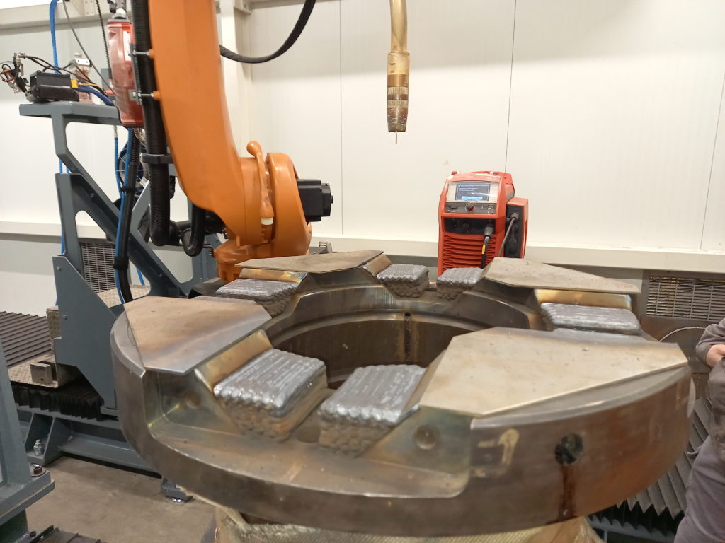
The company explains on its website that they can process parts up to ten by six by five meters, with a maximum weight of 20 tons. They currently have a database of about 24 materials which can be increased upon request. According to Joachim Antonissen, Managing Director, their primarily focus is the repair market that may generate millions of savings. One of the repair parts Antonissen shared as part of this dossier is a mandrel bushing. He explained that during the manufacturing process, the “original material was upgraded to achieve a higher strength after repair and thus prolong the component’s lifetime. Repairing the part costed less than one third of the new part cost, while energy consumption and carbon emission were reduced by more than 90%.”
WAAM3D Ltd, a spin-out company from Cranfield University
If you start researching insights into WAAM, you can’t miss the fact the Cranfield University has been at the heart of major developments on WAAM. Following the patent the university was granted in the 20th century, researchers continue to explore the possibilities of the technology via a large collaborative programme called WAAMMat. Last year, WAAM3D Ltd., a spin-out company from Cranfield University, officially announced its first steps on the market through investment from Accuron Technologies Ltd.
“The basics of WAAM are about melting wire with an electric arc. What we do differently is firstly having a wider choice of arc processes to draw from depending on the requirements our partners have (material, geometry, size, etc). Secondly, we have a patented method to hybridise arcs with lasers to achieve both higher deposition rates and greater control over the final geometry. Thirdly, we have another patented method to introduce cold-work into the parts, and improve resulting mechanical properties dramatically to meet the more stringent requirements applied to critical parts”, Filomeno Martina, CEO and co-founder of WAAM3D Ltd told 3D ADEPT Media.
Unlike other players that bring a key expertise in welding on this market, WAAM3D Ltd said its technology has been developed with WAAM in mind – not welding. Their systems integrate a set of sensors that facilitate quality assurance and control, for example in-process live measurement of shape.
Like fellow companies that specialize in the field, the start-up has also developed a dedicated software suite which comprises WAAMPlanner and WAAMCtrl.
The WAAMPlanner is made up of a CAM package in which the engineer can draw the trajectory of the printing process with embedded process parameters based on the CAD of the part. WAAMCtrl is described as the “brain of the process”. It enables the machine supervisor to monitor the process from anywhere, whilst the part building data gets stored safely.
“We also manufacture wires designed for WAAM, with an incredible quality in the resulting deposition. Therefore, the user experience is consistent with what you would expect from such a futuristic, amazing technology that will no doubt change manufacturing”, Martina states.
While the start-up can’t share some images of their application due to confidentiality, Filomeno Martina said one of his favourite applications is the titanium fuel tanks for satellites the team achieved in partnership with Airbus Defence and Space as well as the work performed at Cranfield in partnership with BAE Systems on the massive Eurofighter Typhoon titanium frame.
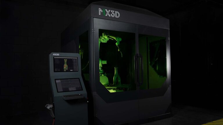
MX3D, from 3D printed steel bridge to a portfolio dedicated to WAAM
The whole industry discovered MX3D when the team unveiled the 3D printed steel bridge they built over the Amsterdam canal using Robotic Wire Arc Additive Manufacturing. Their journey in the industry started in 2014 in Joris Laarman Studio, a Dutch design agency working with new technologies such as 3D printing.
Over time, the company has continuously explored new applications through collaborations with other entities and has been enhancing its solutions. A recent investment round the team secured, reveals that the company has been developing the M1, Metal AM System and MetalXL, software package, dedicated to WAAM.
The Dutch manufacturer told us that their process is very similar to robotic welding. However, rather than placing just a few welds, components are printed by continuously stacking welds on top of each other. The solution therefore comprises three base components: an industrial robot, a welding machine and a software package (MetalXL) that ties it together and transforms it into a 3D metal printer. “These robots can print in almost any metal that is available as a welding wire and the printed objects range from football-sized up to car-sized items. Next to the MetalXL software to program the robot and welding machine to print the CAD-design into a metal object, we now also have developed and connected a MetalXL Control System to monitor, control, and log the full print process in real-time at high resolution”, MX3D notes.
The MX3D team is a true example of a company that learns on the ground. As a matter of fact, their first application – the MX3D Bridge – revealed pain points such as the need for combining various hardware devices with multiple software packages, and a lot of manual coding to achieve optimal print results. The project also raises the interest of other industries in WAAM, which in the end, inspired the development of MetalXL. This solution can “turn an existing robot and welding machine into an industrial-grade 3D metal printer within a day”, the company states. Once users have uploaded their designs, they can choose their ideal material for production (from a material library or custom alloy), select various printing strategies and set relevant process parameters.
Apart from the MX3D bridge, we have also reported through our online media, on other applications achieved by the company. They include for instance, an optimized robot arm, a high-strength structural steel connector made in collaboration with the Japanese architectural, engineering, and construction firm Takenaka, and two printed bicycles. The latest to date is a stainless steel propellor on an 8-axis robotic system. With a total weight of 70kg, the propeller required 24 hours of print time. It confirms one of the key reasons why manufacturers can be interested in robotic WAAM technology: reducing manufacturing lead-time, in particular for custom of small series productions.
“The best way to apply and use additive manufacturing effectively is to start printing. We have learned by doing, trying out new ways to achieve higher quality and printing very different applications for a variety of industries. With our MetalXL technology, we now enable others to also start 3D metal printing in-house”, the company concludes.
AML3D and its Arcemy®
Founded by Andrew Sales in 2014, AML3D Limited is an Australian manufacturer who has been developing a Wire Additive Manufacturing or WAM® technology named Arcemy®. After experiencing the traditional arc welding process, the founder has been researching, developing tools and processes to enhance the Wire Additive Manufacturing process. His research led to the development of the ARCEMY® print module which is being commercialized today.
“Born from traditional welding processes, AML3D’s emerging WAM® technology is adaptable, allowing for an extensive range of capability to manufacture by means of point-to-point welding (i.e. pipe welding) through to additive metal layering (metal 3D printing) to fabricate near-net parts in a free-form environment”, the company states.
The company’s Direct Energy Deposition (DED) technology uses a variant of Wire+Arc Additive Manufacturing (WAAM). Its ARCEMY® technology combines the capabilities of welding science, robotics technology, metallurgy and the company’s proprietary software WAMSoft® and AMLSoft®. Interesting fact, the manufacturer can remotely monitor and/or manage the ARCEMY® Print Module from the Central Control Room located in Adelaide (Australia).
Among the key features that may help the ARCEMY® system distinguish itself from others of the same range, one notes that the certified manufacturing process WAM® uses certified wire feedstock for manufacture, which is sourced locally, allowing for production to stay on-shore.
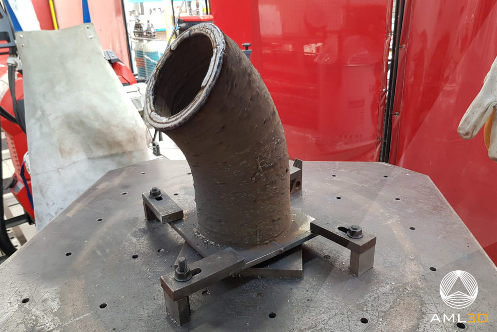
The Australian expert ensures that, due to the manufacturing process which has been supported by NATA testing, WAM® steel printed parts are stronger than forged. From a materials perspective, “up to 80% material waste can be saved when compared to traditional subtractive manufacturing and there is also no consumable wastage, as 100% of the wire consumable is deposited for the near net part/shape being produced”, the company told 3D ADEPT Media. AML3D has already achieved several applications such as an elbow pipe or a propeller. The company points out that WAM® printed parts can be printed on-demand – in a few weeks – and 3D printing maritime applications can receive official verification from DNV.
GEFERTEC: more than just another metal AM alternative
GEFERTEC is one of the machine manufacturers Verlinde mentioned earlier when talking about machine tool-based WAAM systems. Founded in 2015, the German company chose the 2017 edition of EMO Hannover for its first public appearance. At the time, the metal AM market was still dominated by powder-based technologies. For GEFERTEC, coming to the metal AM market was not only a means to provide another metal alternative to manufacturers who were embracing AM technologies, it was also giving manufacturers who were used to conventional manufacturing processes, the possibility to choose between a milling machine and a metal 3D Printing machine.
Like machine manufacturers here, GEFERTEC delivers a completely integrated WAAM process that includes software and machinery. The company explains that their arc-and wire-based process that works with their dedicated CAM software. Here, a build-up strategy for the component is determined and the G-code for the arc-machinery is created.
“Then, the near-net-shape part is printed fully automatically and in a controlled manner. Through the arc the wire is melted and layed down layer by layer. The finishing process of the printed near-net-shape part is then to be realized on a separate milling – or drilling machine”, the company said.
From a materials perspective, one notes that up to 600 cm³ per hour can be produced depending on the material used, be it steel, nickel-based materials, titanium or aluminum. The company also ensures that material utilization is highly optimized compared to metal-cutting manufacturing processes, which enable the operator to save up to 60% in material costs, especially for expensive materials such as titanium.
While no information is shared about how large 3D printed workpieces can be when using a GEFERTEC machine, one interesting application the company shared for this dossier is a project that was conducted for Deutsche Bahn AG. The project required the use of their 3DMP® process for the fabrication of mobility-relevant spare parts that are no longer available from stock and sometimes had extremely long delivery times. “A typical component is the secondary roll stop required in the bogies of ICE trains. This component limits the transverse play of the railroad car body and thus ensures the safe cornering of the trains in tight track curves”, the company outlines.
With years of expertise behind and many more ahead, GEFERTEC prides itself on being an end-to-end WAAM manufacturing solution that develops and qualifies the individual application for each customer to help them successfully implement WAAM into their production.
This dossier has first been published in the 2021 May/June Edition of 3D ADEPT Mag.


