

The article has been updated to reflect the fact that “most industrials often have in mind the use of machines with build volumes around 1 m3”.
Most adopters of Additive Manufacturing (AM) share the same dream: being able to achieve scalable, (high-volume) production. Here is the thing, to make this dream a reality, most industrials often have in mind the use of machines with build volumes around 1 m3. As Large-Format Additive Manufacturing (LFAM) is gaining momentum, we are entitled to ask ourselves how and/or if LFAM can also be considered a viable production candidate.
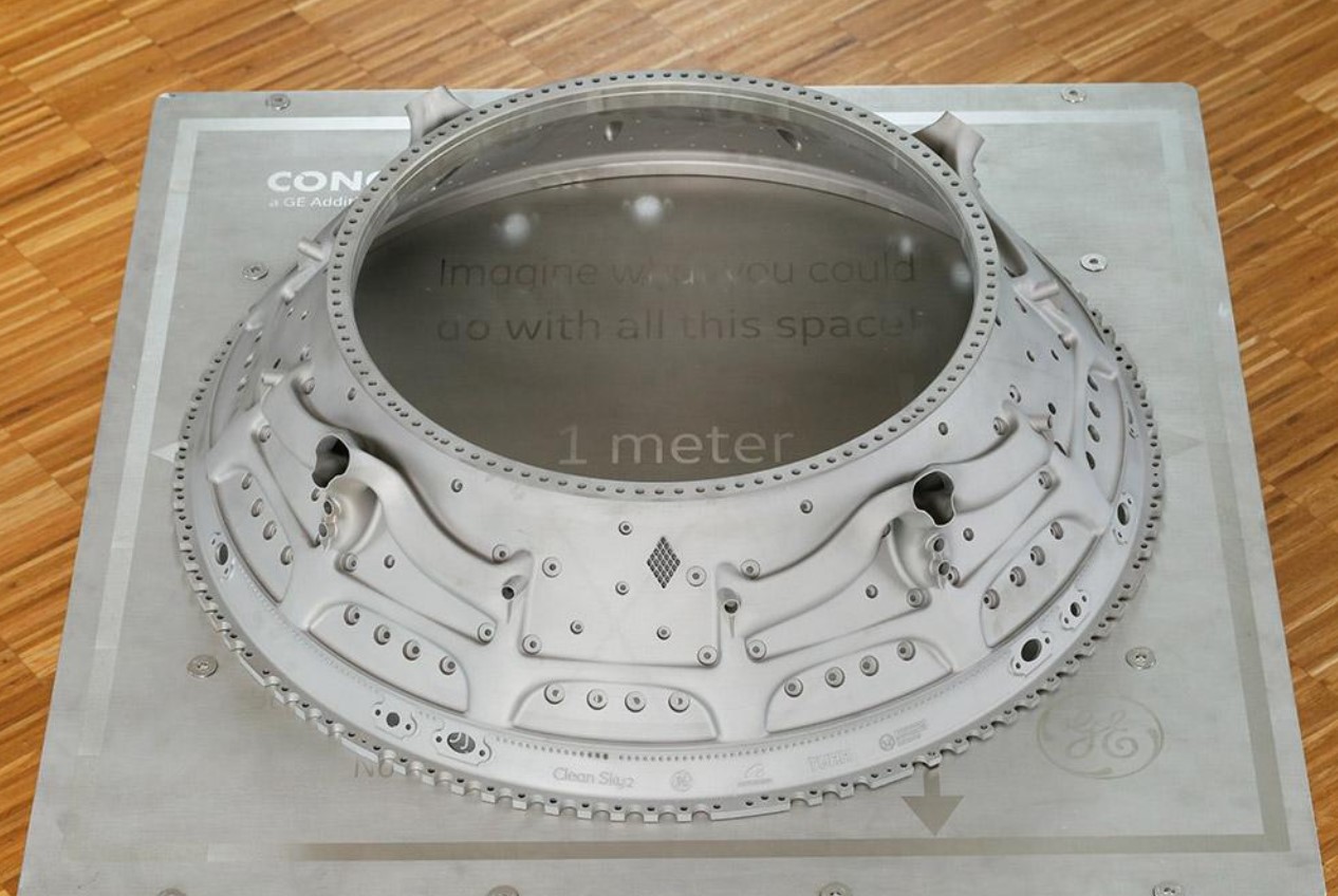
While everyone agrees that Large-Format Additive Manufacturing (LFAM)/ Large-Scale AM is about size, the specifications of applications’ size have always been subject to interpretation. As you may have seen above, we have already disqualified machines with build volumes around 600 × 300 × 600 mm (23.62 × 11.81 × 23.62 inch) as we are looking to explore the production candidacy of machines that can produce yacht hull molds, autoclave tooling, massive 3D printed torches like this one, life-size furniture, boats or even houses. The key measuring element is therefore the ability of the 3D printer to produce large components in a single print run, as opposed to producing several parts that need to be assembled.
The size issue cleared up, let’s remember that as any manufacturing technology qualified for an industry 4.0 environment, LFAM also aims to scale up manufacturing operations while taking into account speed, precision, mechanical strength, ease of customization, etc. For such industrialization to happen, technology providers need to provide clear indications on how to address the challenges that slow down the adoption of the technology. Among the wide range of technical processes that can achieve large-scale applications, one tends to realize that the main challenges to address often turn around three key aspects: software, materials and costs.
The dossier below aims to help industrials:
- Understand the major differences between designing for Large-Format AM and designing for a “standard AM process”
- The key material considerations that could open up (new) large-scale AM applications
- Understand the common pitfalls of large-scale additive manufacturing and where exactly the cost consideration stands in the midst of all of this.
To discuss this topic, we have relied on the expertise of Justin Ferguson, Autodesk Senior Solutions Engineer for the software part, Kyle Calvert, Composite Applications Engineer at Ingersoll Machine Tools for the materials and costs standpoints, as well as Andy R. Bridge, Director of Business Development at Additive Engineering Solutions, LLC for the user perspective.
Designing for LFAM
As detailed in our 2023 International Catalogue of AM Solutions , we identified three types of large-scale AM technologies – each of them having a wide range of sub-processes:
- Extrusion-based technologies where one finds pellet material extrusion (FGF) and filament material extrusion (FFF) processes,
- Powder processes, a category that includes powder-bed fusion approaches, binder jetting and material jetting processes and even cold spray processes,
- And Directed Energy Deposition (DED) processes where we identified Electron-beam additive manufacturing (EBAM), Laser deposition welding (LDW) and Wire arc additive manufacturing (WAAM).
Interestingly, even though some powder-bed fusion processes can fabricate parts larger than one cubic meter, using multiple lasers and larger, multi-area powder bed, the biggest breakthroughs in terms of size come from a growing adoption of DED and in particular WAAM-based processes.
As far as design is concerned, knowing the different design tools in the DfAM toolbox– is one thing, making wise use of them is another one, especially when you know that each AM process and each machine comes with its share of challenges.
While he acknowledges the peculiarities of each machine and each process, Justin Ferguson from Autodesk outlines that “one task that is universally difficult, independent of process, is recognizing areas (during the design process) where there may be a collision of the printing hardware with sections that have already been printed, or non-printed items.”
The good news is that when one uses an LFAM process, one has the ability to 3D print in one piece, which eliminates assembly labor, speeds up production, and increases structural integrity because there are no joints or seams.
How do you develop a strategy to safely increase the scale of your 3D print?
Ferguson identifies five focal points that may help the designer to differentiate designing for LFAM from designing for a “standard AM process”: the machine itself, the shrinking of part size during or after printing, the dependence of strength upon the print direction, the division into separate planar sections as well as the need for inserted, non-printed materials.
He details the reasoning behind each of these considerations below and shares a couple of tips to address issues like shrinking during and/or after the printing process:
“Depending on the LF-AM process, metals (DED, Directed Energy Deposition), plastics (FFF, Fused Filament Fabrication/FGF – Fused Granule Fabrication), aggregates (clay and concrete), and others, different strategies for design become critical to adopt.
- In small-scale additive, we normally have a fixed machine with a single coordinate system and a fixed build envelope. With large-scale, we might be using a robot system, or printing on top of another part, but usually, we don’t have a fixed coordinate system or a fixed build volume. While desktop printers often only move in three axes, large-scale printers often have more axes of motion, whether that’s to move on a track or tilt the tool head. These large format processes performed with multi-axis-capable machines add the ability to create features that are not dependent on overhang angle. This enables us to think outside the ‘regular AM process’ of design for additive manufacturing (DFAM). For example, building features on features, and designing without support structures becomes possible, but can introduce new complexities such as how to slice, surface prep (when building features on features), etc.
- Most LF-AM processes will see a shrinking of part size during or after printing due to conditions such as the cooling of metals and thermoplastics or drying/curing for aggregates and thermosets. Also, as LF-AM prints increase in size, upper layers ‘squish’ lower layers if they aren’t cooled or cured adequately.
If, by design, there is a stop during printing and then restart, such as printing a new feature, or allowing for adequate cooling, the part size and shape are likely to change before we continue.
In Autodesk’s Birmingham Technology Centre we use a thermoplastic pellet extruder fitted to a Kuka 6-axis spherical wrist robot. During one project, we determined that the best way to accurately continue was to over-print and then cut away to a known height using a milling spindle, then restart printing. This is a major difference for LF-AM, because separating the model into print sections, determining overbuild amounts, then the machining amount, all need to be accounted for in the design process. If hybrid (additive and subtractive in the same setup) is not an option, then the shrink amount of the print sections is very important, as is determining where to stop and for how long, so the shrink is predictable and compensatable.
- Another area that LF-AM is quite different from ‘regular AM’ relates to strength being dependent upon the print direction. In a laser powder bed-style machine, for example, the pattern that the laser sinters can change the grain structure and resulting strength. One of our customers, using a powder laser machine, found they could achieve a better grain structure if the whole part was created in one continuous path. The desired grain structure can propagate along continually with consistent speed and constant heat.
- When creating complex geometry such as a bent tube or other complex shapes, a decision could be made to divide into separate planar sections, each with a different build direction – like building a tube with wedge sections. Or an engineer might decide to change the build direction on every layer, and modulate the speed, feed, or other process parameters to achieve a non-planar layer shape.
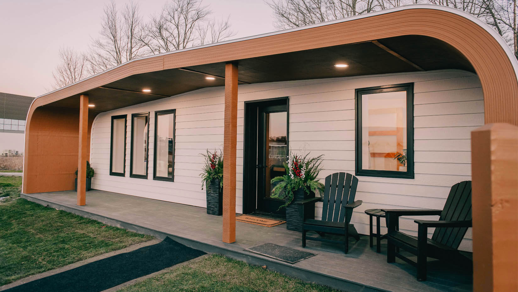
- When considering some of the largest prints, such as homes, there is a need for inserted, non-printed materials. Windows, doors, HVAC, electrical, posts, beams, and other items may need to be accounted for in the DFAM process. If the non-printed materials are integral for the structure, such as posts or beams, determining when to stop a print to then insert these, and make sure they won’t cause collisions with the deposition equipment later, are required steps that are unique to this LF-DFAM use case.”
What happens when your part is just too large for even the largest machine?
Needless to say that the larger the final part is, the more challenging the print. The only option at this point consists in splitting your model into 3D printable components that you will assemble thereafter. Splitting your model directly in your CAD software is a great idea as one can directly design alignment aids, avoid cuts that go directly through specific areas and select cuts that are not located in fragile areas of the print.
For Ferguson, “physics really starts to play a role as parts get bigger. For instance, a wall structure will need to be designed differently if your bead is 1cm wide vs 15cm wide. Think about the weight of the part as layers increase. For DED and other processes, bottom layers can squish or wall structures can even buckle with the tremendous weight of large parts.
In the case of FFF/FGF, if printing in a non-vertical or non-planar orientation, as weight extends out there is the possibility of both compression and tension in layers. This could cause failure in prints and should be accounted for in the design process, which is much more difficult as part size increases.
Lastly, determining if support structures are needed and how they should be applied really becomes quite a difficult design question with large final part sizes, like printing buildings or rockets. If there are supports, they have usually been designed very specifically.”
Key material considerations for LFAM applications
Materials and costs have always been mentioned as the biggest challenge in AM – no matter what technology is used. These challenges are the same if not exacerbated for LFAM as applications span different technologies.
As far as materials are concerned, surface roughness, damage tolerance, inferior fatigue & tensile strength, etc. are a number of problems that may affect a 3D print. Those problems are often linked to an inconsistency in material properties. Whatever the process used, these problems can still occur when fabricating LFAM applications.
“There can always be a defect. Sometimes, when you’re printing, it’s hard to see where the defect is. For a lot of parts we make – most of our parts are for the aerospace industry -, we make a mold or a hot forming tool; those parts that will allow the customer to create the end-use part. And when those problems occur, you add a factor of safety. So, even if there is a defect that alters material properties, you still have a strong enough part at the end; and we combine that with non-destructive testing,” Calvert, Composite Applications Engineer at Ingersoll Machine Tools states. According to Ingersoll’s expert, there is a certain amount of deflection that is allowable in a mold during the fiber laying process that is allowable to still produce a high quality part. Since their printing process aims to replace metal tooling with large format additively manufactured polymer tooling, the manufacturing process should withstand the forces of the layup process without deflecting (temporarily changing shape) over a certain amount. This deflection can be measured in order to quantify if the tool meets the requirements needed for this manufacturing method.
On another note, it’s also possible to identify these defects as they occur by tracking the process parameters using thermal and vision systems. However, because it’s such a new technology, most machine manufacturers in this area are still in the data collection phase. As we get more data on what happens during the print process, we could use machine learning to identify the parameters that needed to be adapted and address the problem to predict future errors,” Kyle Calvert adds.
Keep in mind that Calvert shares his expertise here with polymers in mind – especially pellets used for Ingersoll’s polymer extrusion technology whose build volume is greater than one cubic meter.
Needless to say that solutions to address material inconsistency vary from one manufacturer to another, and from one technology to another.
Additive Engineering Solutions, LLC is currently using LFAM for series production. While he didn’t exactly precise the type of LFAM they harness, Andy R. Bridge explains they currently “rely on statistical-based process control during the LFAM printing process followed by dimensional and sometimes vacuum integrity inspections” to address these inconsistencies.
Moving forward, materials that will bring a substantial advantage in terms of performance and resistance (to UV and water in particular) are likely to open new applications in the LFAM segment. To these items, Calvert adds materials with lower cost and materials with better isotropic properties. The Composite Applications Engineer lays emphasis on the fact that some of these requirements can be more stringent for certain users – like aerospace part manufacturers.
“For aerospace part manufacturers, the Coefficient of Thermal Expansion (CTE) is not quite as good as metals because the material is a polymer. When you’re trying to put the mold into an autoclave process, it works more than metal would. The better those engineering polymers get, the closer we get to replacing metals in mold making,” Calver notes.
Apart from these engineering requirements, it should be noted that recycled/repurposed/upcycled material formats are the next areas of interest that manufacturers would like to see expand.
A hard time for plastics, in general
“Plastics in general have a hard time being outside,” Ingersoll points out. “Material experts have been working on adding additives into the plastic so that it can better withstand UV and water, but until we get a plastic that can last many years outside, under the sun or rain, it’s going to be harder to adopt LFAM at a wider scale.”
In addition, cost is another key item that prevents a larger adoption of LFAM. For our expert, machine manufacturers in this niche segment currently compete with conventional manufacturing processes, wood or other cheap prototyping methods of making parts.
This means that:
- If production ramps up and the price of materials drop,
- If newly developed engineered parts with better material properties enable the manufacture of end-use parts and not just molds or tooling,
- There is a great chance that more industries adopt pellet-based LFAM technologies.
Materials used in other processes
If we didn’t identify any peculiarities for other processes, that’s simply because there aren’t any specific issues the user of a standard AM process is not already aware of. As these materials are usually the same but used at a larger scale, the main problems that require specific attention are usually seen at the design and/or printing process levels.
To that, Autodesk’s Ferguson warns that “there is a trend toward larger-format powder bed machines, which requires greater care during the build preparation, toolpathing, and simulation stages because as printed parts get larger, the cost of failure dramatically increases. Predicting potential issues before starting the print, a specialization of Autodesk Netfabb, is of tremendous value”. “Netfabb also allows for the simulation of DED toolpaths for thermal and mechanical analysis. This enables users to look at the internal temperature of the whole model as it is being printed, and aid in deciding when to add breaks in the toolpath for cooling. It even can predict what the final distorted shape might look like,” he adds.
That said, Fusion 360 has other tools that can aid in LF-AM as well, for plastics and other materials that can have complex infill patterns. The software provider recently introduced Volumetric Latticing, a tool that enables users to create infill structures that can provide strength while using less material, meeting this way cost, weight, and/or sustainability requirements.
The common pitfalls of large-scale additive manufacturing and other cost considerations
Just like AM in general has led many industrials to have a misleading appreciation of the technology, LFAM processes may often induce disguised expectations for those who are not familiar with the different technologies.
Based on insights shared by Ferguson, Calvert and Andy R. Bridge, we can already point out the pitfalls below:
- LFAM doesn’t replace existing AM processes; it complements them. For large parts, this is not replacing other forms of AM; it is replacing hand-crafting the parts from scratch or traditional subtractive processes.
- Since most LFAM processes have a robotic feature, people often think there are plug-and-play systems. The operators always need to be well-trained. The more processes will be automated, the quicker the training process will get.
- Bigger prints and more material mean it’s expensive to have a print failure. Process test prints to fully understand your process, try to know your problems before you have them. Determine if any bad sections can be cut out and/or repaired.
- Most LF-AM machines bigger than about 1m x 1m x 1m are not mass-produced machines. Instead, they’re typically custom systems or in their early years, so they can be tricky to operate, requiring bespoke software.
- Not knowing a process well enough could be seen as a pitfall, costing more (waste), introducing stress concentration points, under-printing or over-printing, etc. Material flow rate out of a nozzle, for example, adds its own difficulty and isn’t specific to one process. In a lot of cases, it is simply not an option to pause or change the extrusion speed on the fly, or it’s very wasteful to do so.
- It’s worth keeping this in mind: in addition to the capital costs for the Large Format printing equipment, there are many other areas of cost to consider. Some of these are software, polymer expertise, design expertise, process control, engineering investment, and training. Certain end-use products like aerospace tooling also require large-scale precision CNC mills.
- Last but not least, sometimes, it’s not about costs, it’s about lead times.
To date, industrialization is still a goal to achieve for those who explore the use of LFAM technologies. Use cases already developed with the processes range from prototypes to small series productions across applications within the aerospace, marine and construction industries.
What we find the most interesting is that there is momentum in the construction industry –where there is a need to reduce man-hours – and applications in this field reveal that concrete 3D printing is not always the only production candidate that can be used to achieve that.
This dossier has first been published in the May/June edition of 3D ADEPT Mag.
A few words on the contributing companies
Additive Engineering Solutions (AES) is an advanced manufacturing company that provides large format polymer additive manufacturing (LFAM) solutions. Whether it’s 3D printing large tools and molds for the composite aerospace & defence industry or printing large end-use parts for the AUV markets; AES ambitions to demonstrate the ability to manufacture a variety of products with more efficiency and customization than traditional methods. The company is looking to explore vitrimer materials in the near future for LFAM applications.
Autodesk is a software company that provides several solutions that can assist in LFAM, ranging from simple 2.5D slicing to multi-axis, non-planar slicing, the ability to drive desktop machines, hybrid machines, and robots, and the ability to simulate metal prints in order to detect possible issues before getting on the machine. Autodesk offers software that covers most of the additive space, including LFAM. One issue seen across industries is the idea that data is separate, usually programming in a separate software from the design. For additive, especially LFAM, having to switch back and forth from separate design and programming packages for design changes means a lot of exporting and importing. The company’s software solutions are designed to eliminate this issue, enabling a more seamless workflow.
Ingersoll builds large polymer 3D printers and automated fiber placement machines. The company’s portfolio comprises gantry-style printers and robotic 3D printers. All machines are hybrid and can be equipped with printing, milling, automated fiber placement (AFP), or ATL (automated tape laying). Ingersoll also provides contact printing services for aerospace tooling, the marine industry, or life-size furniture applications.


