

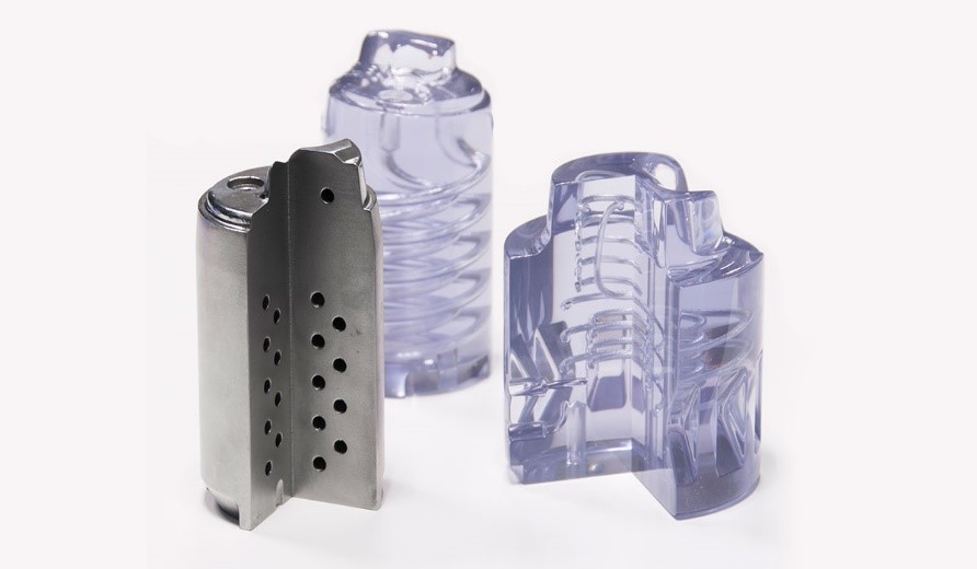
Insert moulding services are one of the main services offered by digital manufacturers. Such a service helps accelerate the development cycle of products across the medical, automotive, consumer products and electronic components industries. The fact is, although operators no longer question the ability of Additive Manufacturing technologies to produce a much-more cost-effective result than conventional tooling and die making, they are still cross-examining what AM technology best suits the production of prototype mould inserts.
The rise of 3D printing has had impacts not solely on the production of end-used parts as a direct manufacturing technology, but also as an indirect manufacturing technology. For example, Additive Manufacturing is sometimes used to create moulds for the purpose of urethane or silicone casting. In other circumstances, it is used to create tools such as jigs or fixtures that enhance the performance of machining cells. This ability to create custom tools for traditional manufacturing processes also extends into the realm of injection moulding, where 3D printing technology is used to create custom injection mold inserts. But when it comes to creating a custom mould insert, which technology is best? We spoke with a couple of digital manufacturing experts to learn more about two of the most popular 3D printing technologies used for this application, material jetting and laser powder bed fusion.
The use of Additive Manufacturing technologies for the production of custom mould inserts
With the goal of addressing the needs of mass customization, AM companies have been exploring their manufacturing processes to produce the tooling used in injection moulding with varied levels of success.
“Theoretically, any AM technology can be used. One might immediately think of extrusion 3D printing which is probably the most widely used technology for prototypes but that’s probably because it is the technology people know the most. There are no reasons why SLS, other powder-bed processes like Electron Beam, or even binder jetting can’t be used. At the end of the day, it’s the results obtained, that matter the most”, Cullen Hilkene, CEO at 3Diligent told 3D ADEPT Media from the outset.
So far, most applications that have been shared by companies were achieved using DLP, SLA, Freeform Injection Moulding, SLS, DMLS / SLM, as well as PolyJet. However, DMLS and PolyJet are the most widely mentioned technologies for such applications, which is why we will only focus on these two technologies as part of this dossier.
That being said, no matter what AM technology is used, the manufacturing perspective reveals that “traditionally, the moulding with metal inserts is carried out with the aim of reinforcing the mechanical properties of the inserts, reducing the cycle time and obtaining moulded articles with a better aesthetic / dimensional quality.”
Furthermore, still according to ZARE’s experts, another manufacturing goal would consist in integrating an item with specific thermal properties, in a mould done with a different material.
Moreover, “another use, more critical, concerns the creation of particular and equidistant cooling channels from the surface. Such cooling channels allow a greater heat dissipation in the unit of time with the consequent reduction of the duration of the moulding cycle and a reduction of the deformations on the finished product, increasing the quality of the final product”, they said.
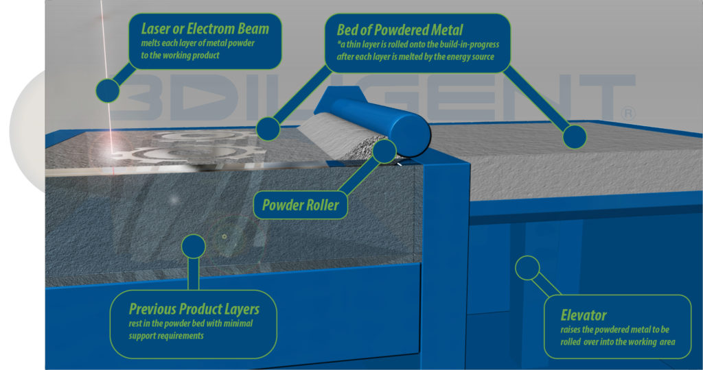
Brief description of DMLS/ Laser powder-bed fusion (LPBF).
First of all, let’s note that, although DMLS is often used interchangeably with SLM or LPBF, it should be noted that DMLS is a trademark of EOS, SLM, a term introduced by the Fraunhofer Institute in 1995, while LPBF is the generic name given to the manufacturing process. That’s why the name “laser powder-bed fusion” will be the one used in this feature.
Let’s erase any confusion that may arise here: DMLS which is meant for Direct Metal Laser Sintering, features the word “Sintering” when in reality, it works by melting. In the same vein, LPBF uses the word “Fusion” while one cannot melt a plastic; it needs to be sintered.
In any case, for those who are not familiar with it, this manufacturing process enables the production of “net and near-net shape parts directly from a digital drawing file with dimensional tolerances of less than 0.1 mm” through an interaction between a high-energy laser and a metal powder feedstock.
During the manufacturing process, the machine fills its build chamber with an inert gas and thereafter, heats it to the ideal printing temperature. Based on the layer thickness defined upfront (typically 0.1mm thick of material), a thin layer of powder is applied to the build platform. Once the fiber optic laser (200/400 W) scans the cross-section of the part, it allows for the melting of the metal particles together. A new layer of powder is spread across the previous layer using a roller. More layers or cross sections are fused and added. The process is repeated until the 3D printed part is completely built.
Brief description of PolyJet/ Material Jetting
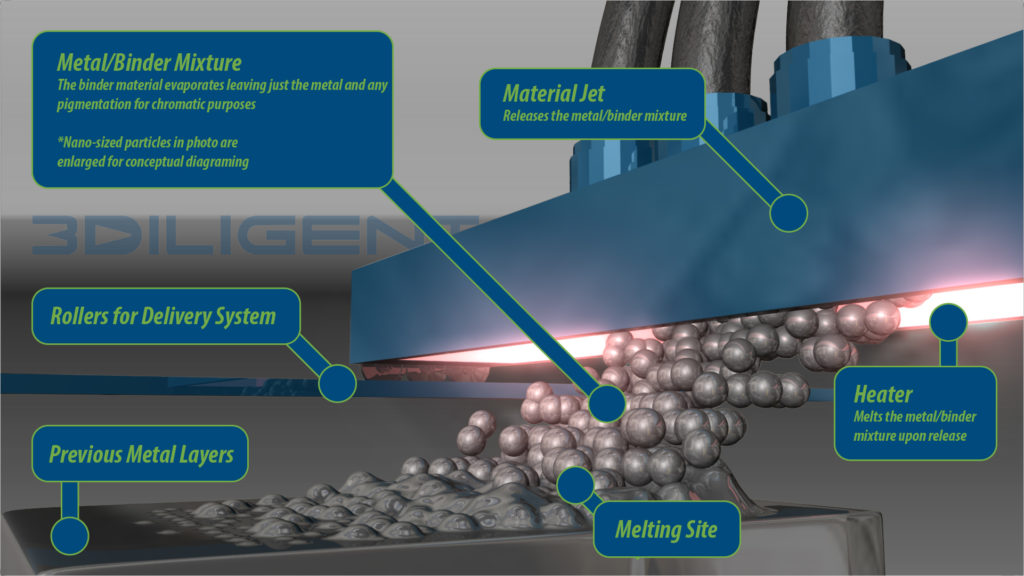
PolyJet is a manufacturing process that works either on a continuous or a Drop on Demand (DOD) approach. With a process similar to a two-dimensional ink jet printer, it fabricates parts by jetting thousands of photopolymer droplets onto a build platform and solidifying them with a UV light.
In the 2000s, Objet-Geometries was the first company that developed a 3D printer with that process, patented it under the name PolyJet. Eleven years later, in 2011, Stratasys acquired Objet, and since then, has been expanding its range of products to Material Jetting (MJ) solutions.
Today, the name PolyJet remains associated to Stratasys 3D printers. However, Stratasys is not the only company that develops industrial 3D printers based on this process, which is why “Material Jetting” will be the term used in this process, as it refers to the general name of this manufacturing process.
The printing process begins with pouring the photopolymer resin into the material container. That resin must be heated (to between 30 and 60 °C) in order to reach the appropriate viscosity.
As the X-axis carriage starts to move across the build plate, the print heads begin selectively jetting hundreds of tiny resin droplets. As the UV light sources follow the print heads’ trajectory and instantly cure the sprayed resin. Once an entire layer is completed, the build platform drops one layer in height and the process is repeated until the part is entirely formed.
With technology advancements, machine manufacturers have developed 3D printers with multiple print heads in order to achieve multi-material printing. Depending on the machine used, multi-material 3D printers can enable dissolvable support material or multiple varieties or colours of functional material.
Furthermore, over time, several types of Material Jetting technologies have been developed in order to meet the diverse needs of industries. They include for instance material jetting processes that work with resin and cartridge; material jetting processes that work with ink; material jetting processes that work with wax and cartridge or even material jetting processes that work with metal and cartridge.
“While it is important to distinguish between material jetting with metals and plastics, it should be noted that mould inserts are usually made out of metals”, Hilkene notes.
However, this does not mean that, one cannot produce a mould insert in plastic. As a matter of fact, the aforementioned AM technologies that can be used to produce mould inserts include FFF which processes plastic materials. Here is the thing, we need to understand what explains the move from traditional manufacturing processes to additive manufacturing processes; and thereafter the choice for one specific AM technology over another.
In this case, many of the traditional struggles with design for injection moulding in metal presented themselves in the design of plastic tooling. However, most of these issues are often amplified due to the poorer surface finish of a 3D printed mould when compared to a similar metal mould, hence the choice for a metal AM process for such production.
In addition, research shows that 3D printed plastic mould inserts have revolutionized mould manufacturing in the plastics processing sector. The low mould costs as well as the rapid implementation of design changes were very appealing to users at the beginning, until they realized the results were not always durable. Furthermore, due to higher temperatures of the materials and high injection pressures, the operating cycles of the 3D printed plastic moulds often decrease. The search for more stable solutions for small series and medium quantities has led many manufacturers to consider metal AM alternatives.
For the production of mould inserts, what will tip the balance in favour of LPBF or MJ?
In order to assess which technology best suits the production of mould inserts, we’ve compared these two technologies based on five main criteria: complexity of the geometry, post-processing, timing, production volume and costs.
This analysis is mainly based on our interview with Cullen Hilkene, CEO of 3Diligent, a company that brings Distributed Digital Manufacturing to fruition. External contributions from other companies as well as research have also helped to bring the most accurate evaluation of these processes.
Complexity of the geometry
It goes without saying that there are some products that are easy to manufacture using injection moulding because of their simple single cavity design and their size. However, it is no secret that AM is appealing because of its ability to produce complex geometries, especially complex cooling channels.
According to Hilkene, LPBF earns a point here, as the technology is suitable for cooling parts with complex shapes. According to the expert, the challenge at the manufacturing level consists in keeping a uniform temperature on the surface of the mould to cool the hot molten material inside the cavity. Not only does this cooling process take time, but it often leads to high costs of production. To dissipate heat in a very short period of time during the manufacturing process, engineers have to reconstruct the cooling channel near the surface of the part. Compared to traditional milling, LPBF brings significant improvements at this level as it gives engineers the possibility to design free geometries, melting layer on layer metallic powders, while ensuring a steady dissipation of heat across the chamber.
Post-processing
Certain AM technologies do not require post-processing once the manufacturing stage is over. In this specific case, LPBF loses a point as the technology “does not always print as smooth as the other manufacturing processes, hence the need for a post-processing step at the end of the printing process”, 3Diligent’s CEO notes.
On the other hand, for applications where wear resistance is no longer the most critical factor, Material Jetting is acknowledged for delivering 3D printed parts with high accuracy and excellent surface finish.
Time, costs and volume production
Compared to conventional manufacturing processes that often take several weeks, both AM processes enable operators to save time. Nevertheless, when comparing those LPBF and MJ processes, one notes that LPBF is more costly and requires more production time than MJ.
Not only does the manufacturing process with LPBF require an extra post-processing stage – which is already considered as the most expensive stage of the overall production process -, but sometimes, the production of mould inserts should meet customer-specific solutions that can’t be defined upfront.
As far as volume is concerned, one of the first steps at the production level usually consists in considering whether a mould is going to be used to make 30 or 30 000 parts. Once the prototypes have been approved, conventional manufacturing processes usually become the ideal option for mass production. Nonetheless, between the two manufacturing processes that we analyse today, one notes that Material Jetting best suits the production of low-run moulding.
So, what should we keep in mind?
The table below provides a quick look at the items that have been assessed to compare LPBF and MJ for the production of mould inserts.
| Technologies/Analysis criteria | Main competitive process in the traditional range | Complexity of the geometry | Post-processing | Time | Costs | Volume production |
| Laser powder-bed fusion |
Traditional milling |
Ideal for complex shapes | Additional post-processing stage | More production time | Costly compared to MJ | Big volume production |
| Material Jetting | Excellent accurate results | No intensive post-processing stage | Reduced production time compared to LPBF | Less expensive than LPBF | Ideal for low-run moulding |
And now?
We can’t say for sure that the challenges surrounding tool design within injection moulding industries will all be addressed anytime soon. However, one can testify to the various manufacturing processes that can now produce a tool having complex geometries, “with accurate dimensions, feeding of material into cavity, cooling channels and easy ejection of solidified part”.
Two of these technologies have been assessed today. What we will keep in mind is that 3D printed mould inserts can be produced in fast turnaround times (1-2 weeks as opposed to 5+ weeks with traditional milling). Most importantly, AM technologies are ideal for mould designs where changes or iterations are probable, for parts that are relatively small (less than 150 mm), and for low production quantities.
Despite these advancements at the production level, one should note that we do not always know whether or not, these 3D printed parts are brought to the market as a standalone product or as part of a bigger structure. Not to mention that, there is no clear indication of the lifecycle of a 3D printed mould.
This exclusive feature has first been published in the 2021 July/August Edition of 3D ADEPT Mag. Featured image: 3D Hubs


