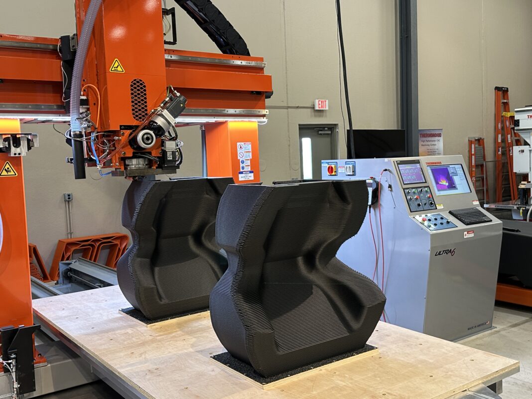
The growing demand for large 3D printed parts implies that Additive Manufacturing users should set realistic expectations when trying to scale up their operations. While the constant comparison between Large Format Additive Manufacturing (LFAM) and desktop 3D printing processes is often inevitable, one must also keep in mind that LFAM comes in many shapes and each of these approaches requires its recipe for success. A conversation with Thermwood’s Scott Vaal helps us understand some of the key elements of success with the LSAM technology.
Acknowledged for its CNC router technologies, Thermwood is one of these companies that no longer needs any introduction in the world of Additive Manufacturing. The company has made a name for itself in the field of LFAM – with its Large Scale Additive (LSAM) technology – and continues to intrigue with the recent launch of an AM process that does not 3D print.
As AM grows in maturity, it’s crucial to understand the challenges inherent to each technology and the solutions that can be explored to address them. Indeed, despite the common hurdles some technologies may have, I strongly believe the way each OEM approaches the problem makes their technology more attractive or not.
This article therefore aims to understand some of the technical hurdles related to LSAM and the solutions Thermwood puts in place to address them. To do so, we will focus on technical issues that may occur at the design and materials level and during the manufacturing process.
Through his responses, Scott Vaal, LSAM product manager, made us realize that each item of the manufacturing value chain is somehow linked to another one – thus, they do not necessarily require individual solutions/approaches.
When technical issues at the design level affect the manufacturing process
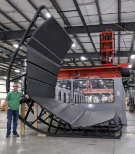
LFAM can expand the design envelope through its ability to print several large parts in one operation. Compared to AM on a small scale, part consolidation and reduced manufacturing time are other factors that play to the strengths of LFAM.
Last year, when we discussed a strategy to increase the scale of one’s 3D print with LFAM, five focal points had been identified to help the designer differentiate between designing for LFAM and designing for a “standard AM process”: the machine itself, the shrinking of part size during or after printing, the dependence of strength upon the print direction, the division into separate planar sections as well as the need for inserted, non-printed materials.
Vaal first draws our attention to the fact that each part is different and should be examined for the best method to use. This means that the size of the part does not necessarily make the design more challenging. Indeed, he notes that in some cases, “it can significantly reduce labor by incorporating as much into one print as possible, but it is not always practical to print that way. Also, there are cases where it is quicker to print the part in multiple sections rather than all in one piece. This is because you must spend at least enough time to allow a layer to cool to the ideal temperature before starting the next one. This means you may be running at a reduced feed rate to print the part in one piece but have the speed and output capability to print 4 pieces at the same time, reducing the print time by a fourth. Of course, this may mean you will have to bond or attach the parts to each other, which also takes time.”
That being said, for the product manager, one uses the near net shape process where one typically prints much larger beads that create larger cusps between the printed layers.
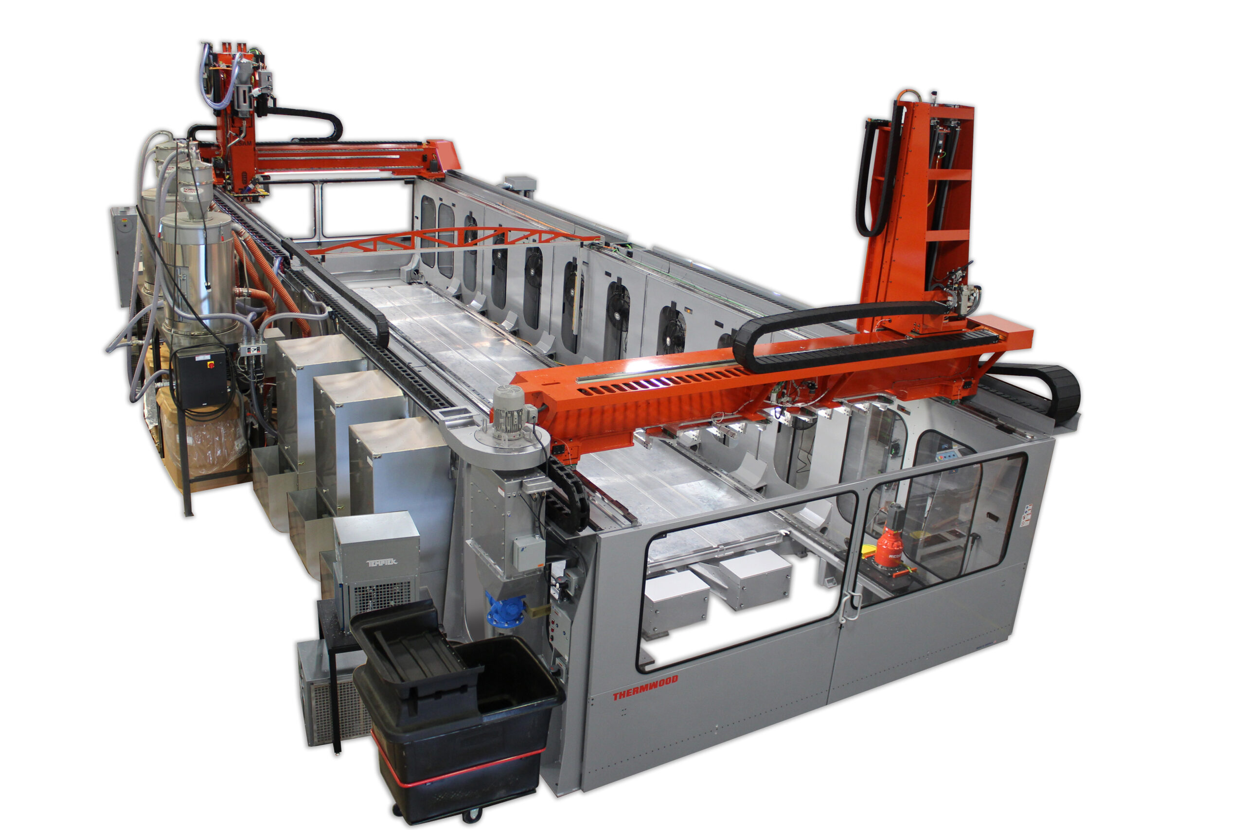
“You will typically print slightly oversized with the intent to post-machine the surfaces that are required to be smooth and accurate, such as the face surfaces of a forming mold or tool. A lot of the time, you will stay away from heavy or full infill strategies and use a hollower method with specific and pin-pointed bracing where needed. This is to keep weight down and to better control large heat differentials within the part which is especially important when using high-temperature materials suitable for autoclave tooling,” he adds.
Besides these focal points, one should keep in mind that elements such as thin walls and small features should be avoided as much as possible. Indeed, the large bead size and difficulty with starts and stops, make these features error-prone. To address this issue, some OEMs or software providers recommend ensuring that the thickness is at least 2x the bead width when designing thin wall sections.
Using the manufacturer’s slicing software LSAM Print 3D, users of LSAM technology can create quality print programs targeted for the LSAM and the large-scale additive. However, Vaal warns that “it is difficult and even impossible at times to create print models that have the proper wall thicknesses needed for the large-scale planar slicing method, especially when you have undulating and complex curved flowing surfaces. LSAM Print 3D can automatically create the print path wall thicknesses for you based on the print bead dimensions you are using resulting in consistent overlaps between bead passes. It will also automatically apply the desired trim stock needed so that you do not have to modify the part geometry just to get extra print stock for machining. With its true CAD environment, you have the freedom to orient your parts any way you need and chose the print method that best fits. It has the tools and techniques to easily add pinpointed bracing and other supports to the print. LSAM Print 3D also gives you the freedom to have unique settings for different areas of the print so that you are not limited to one set of parameters to try and print the entire part. And maybe best of all, it creates the slicing and print programs directly from real CAD formats such as solids, surfaces and sheet bodies so there is no need to create an already reduced in quality .stl file just to create a print program.”
Other difficulties during the manufacturing stage
Warping, temperature control and layer adhesion are some of the difficulties one often encounters during the manufacturing process. If you’re a regular reader of 3D ADEPT Media, you probably already know that Thermwood developed a solution for temperature control.
Interestingly, the key to minimize warping and layer adhesion often lies in the choice of materials used during the manufacturing process. The main factors influencing interlayer adhesion include material properties, recoat temperature, warping forces, and any form of compacting or rolling of the layer post-extrusion. For some applications, materials with low shrinkage rates, and the ones filled with short strand fiber materials could be good options.
As regards warping, Thermwood’s expert explains that “it actually starts with the LSAM’s patented bead board print substrate that provides an important strong initial tack, and then the special surface floats with the part as it cools and shrinks. Then, after the initial layers cool down it holds strong throughout the entire printing process, preventing distortion and stresses that build in other substrates. Also, achieving and maintaining optimal temperatures during the entire print process is important for controlling warp, but maybe more important for providing proper layer adhesion. As [stated above], Thermwood solves this issue with its patented Layer Time Control feature built into the LSAM control system which dynamically controls and maintains proper temperature conditions. Equally important to layer adhesion is the active compaction you get from the LSAM’s patented compression following wheel which greatly enhances interlayer bonding and provides the best results for lateral bead to bead solidity.”
Consistency, “one of the best traits of LSAM”.
While inconsistency in material properties is often one of the key issues to address in a “standard” AM process, users of Thermwood’s LSAM should not face any issues in this regard.
“Our patented Melt Core system delivers the most precise and consistent material output possible and with the patented compression wheel you get the most accurate bead dimensions and consistency in the printed composite microstructures. Being consistent is especially important when printing high-temperature autoclave tooling where we must accurately compensate for anisotropic CTE and other shape changes. This also means we must have material suppliers that can provide consistency between lots of materials. Luckily, we have several suppliers that we can trust to do just that”, Vaal states.
If this article discusses some of the most widely encountered issues faced during a manufacturing process that involves LFAM, it is fair to say this list is not exhaustive. We strongly believe that the more AM users assess Thermwood’s LSAM, the more we will outline specifications and learn lessons that could help ensure a successful product development.
As Vaal points out: “Thermwood is always looking to improve its products, processes and software. We are never sitting still, so it’s hard to tell what may be right around the corner for LSAM innovations. We are constantly working internally and with customers and research facilities to come up with innovative solutions and improvements.”
This content has been produced in collaboration with Thermwood. It was initially published in the May/June edition of 3D ADEPT Mag. All images: courtesy of Thermwood.


