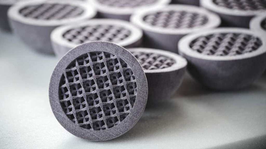
Archive — This 2019 feature compares metal injection moulding (MIM) and metal binder jetting through interviews with Digital Metal, Desktop Metal and ExOne. Roles, market observations and product references reflect that period.
Sinter-based metal additive manufacturing draws on knowledge developed in powder metallurgy, including metal injection moulding. For this 2019 feature, Ralf Carlström of Digital Metal, Larry Lyons of Desktop Metal and John Hartner of ExOne discussed the connections and differences between MIM and binder jetting.
MIM has come a long way since the early days, and its operators have proven that this technology is capable of reliable high-volume production and strong material properties. On the other hand, with the growing adoption of AM technologies that rely on a sintering process as a final production stage, a key focus is often made on “MIM-like” AM processes.
The investigation considers where the processes share knowledge, how shaping differs, and which design and production requirements influence their selection. The interviewees’ descriptions are retained with clarifications where a general claim needs qualification.
All participating companies specialise in metal additive manufacturing. Some of them shared their experience in both MIM & Metal AM.
Whilst this dossier will give a more detailed overview of these technologies, the article aims at guiding prospective users to identify the technology that best meets their needs.
The evolution of Metal Injection Moulding (MIM)
MIM combines injection moulding with powder metallurgy. It uses a metal-powder and binder feedstock to form a green part in a mould, followed by binder removal and sintering.
The feedstock is heated sufficiently for the binder system to flow, then injected into a mould cavity. The metal powder is not melted during this shaping stage.
Like press-and-sinter powder metallurgy, MIM uses sintering to densify a powder-based shape. Its forming step differs: MIM injects a powder–binder feedstock rather than compacting powder directly in a rigid die.
MIM is part of powder injection moulding, which also includes ceramic injection moulding. Part geometry, feedstock behaviour and production volumes influence its suitability.
Description of the process
Developments in feedstocks, forming and thermal processing have broadened MIM applications. The underlying sequence remains shaping, binder removal and sintering.
However, we will keep in mind this explanation of the technology principles from Ralf Carlström, General Manager of Digital Metal:

“The process steps involve combining metal powders with polymers such as wax and polypropylene binders to produce the “feedstock” mix that is injected as a liquid into a mould using plastic injection moulding machines. The moulded or “green part” is cooled and ejected from the mould. Next, a portion of the binder material is removed using solvent, thermal furnaces, catalytic process, or a combination of methods. The resulting, fragile and porous (40 volume per cent “air”) part, is in a condition called the “brown” stage.
To improve handling often the debinding and sintering are combined into a single process. Sintering heats the powder to temperatures near the melting point in a protective atmosphere furnace to densify the particles using capillary forces in a process called sintering. MIM parts are often sintered at temperatures nearly high enough to induce partial melting in a process termed liquid phase sintering. For example, a stainless steel might be heated to 1350 to 1400 degrees Celsius).
Diffusion rates are high leading to high shrinkage and densification. If performed in a vacuum, it is common to reach 96–99% solid density. The end-product metal has comparable mechanical and physical properties with annealed parts made using classic metalworking methods. Post sintering heat treatments for MIM are the same as with other fabrication routes, and with high density, the MIM component is compatible with the metal conditioning treatments such as plating, passivating, annealing, carburizing, nitriding, and precipitation hardening.”
The temperatures, density range and heat treatments in this explanation depend on the alloy, binder and furnace route. Liquid-phase sintering is not required for every MIM material, and process selection must follow the qualified material specification.
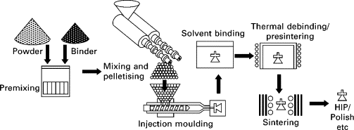
In addition to explaining the process, the description announces a few similarities with binder jetting technology, but that’s something we will discuss in the lines below. First, let’s see how and why this technology increasingly leads engineers to consider metal 3D printing as a much valuable tool in their toolkit.
Constraints to consider in MIM
First of all, components from a wide range of sectors can be created using MIM. A few examples include parts in the medical field, the manufacturing industry, firearms and much more.
MIM production must control feedstock consistency, mould filling, binder removal and sintering shrinkage. Voids, distortion or inconsistent properties can arise when the process is not adequately controlled; these risks do not make MIM inherently a last-resort manufacturing method.
Binder jetting provides another shaping option, particularly where avoiding a dedicated mould or changing geometries is valuable. It must also control density, dimensions and final properties.
Metal 3D Printing adds another option to the engineer’s toolkit
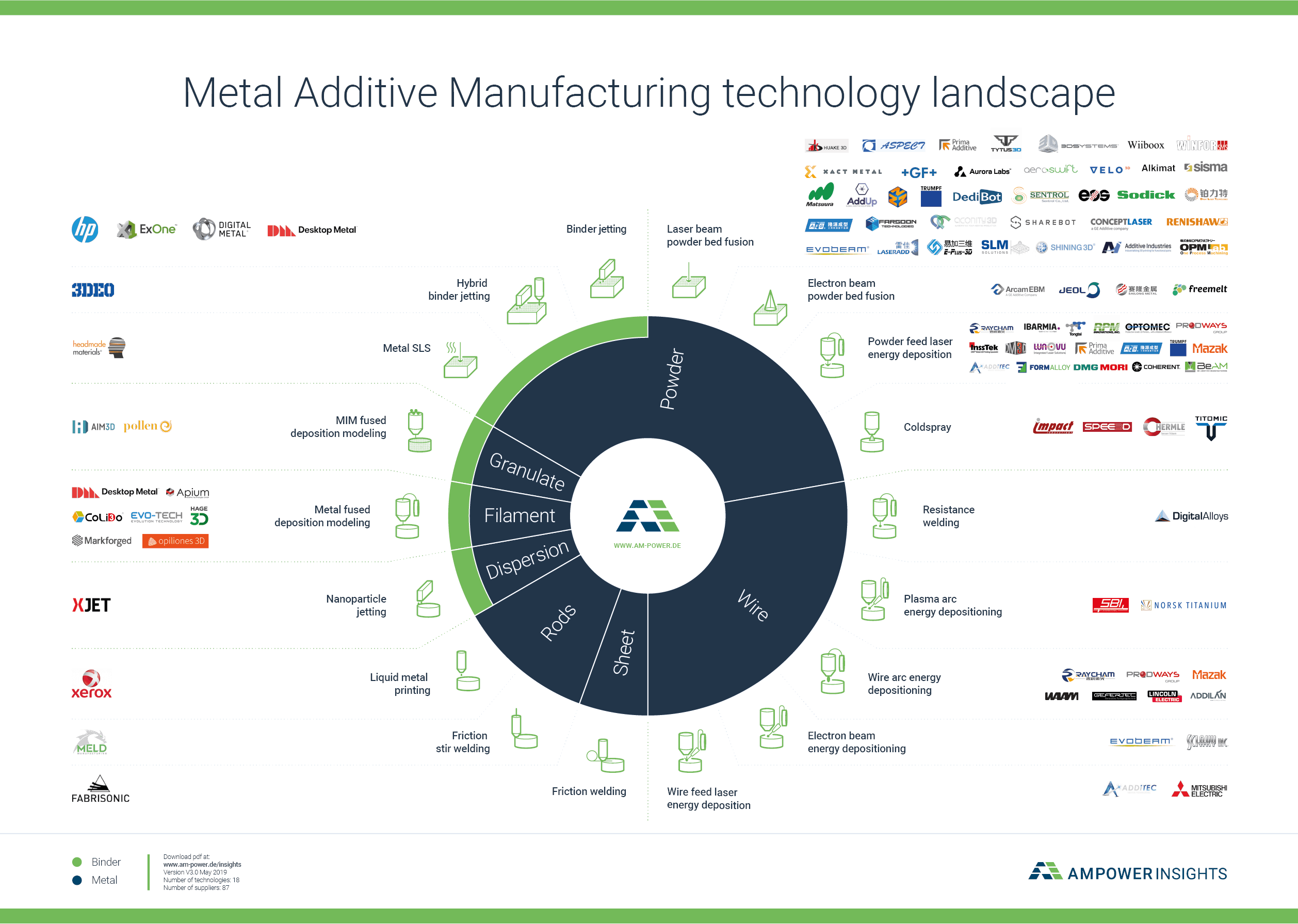
Metal additive manufacturing comprises several processes, with different feedstocks, energy sources and production constraints. This feature focuses on binder jetting.
Binder jetting forms a green body by depositing binder onto metal powder and relies on subsequent thermal processing. It is therefore distinct from processes that fuse metal during the build.
From MIM to binder jetting
Following Ralf Carlström’s explanations on MIM, we realized that MIM & binder jetting share some characteristics in their development.

First, “binder jetting is a metal AM technology that leverages decades of powder metallurgy experience. Thin layers of powder are dispensed, selectively bound, cured, and then sintered to high density. By using the same powders and furnaces as MIM, binder jetting produces parts that meet MPIF Standard 35 for MIM”, said ExOne CEO John Hartner.
Using a powder or furnace associated with MIM does not automatically establish compliance. MPIF’s material standards require the relevant grade, property and testing conditions to be agreed and verified.
“The 3D Printed part is built up from many thin cross-sections of the 3D model. An inkjet print head moves across a bed of powder, selectively depositing a liquid binding material. A thin layer of powder is spread across the completed section and the process is repeated with each layer adhering to the last. When the model is complete, the unbound powder is automatically and/or manually removed in a process called “de-powdering” and maybe reused to some extent. The de-powdered part requires sintering to develop final properties”, adds Digital Metal’s Managing Director.
Binder jetting and MIM may draw on overlapping powder-metallurgy expertise, but their feedstocks and forming methods differ. Powder size, binder compatibility and thermal processing must be qualified for the selected route rather than assumed interchangeable.
Desktop Metal on its side explains how they leveraged the potential of MIM to develop their binder jetting technology, and it all starts with the expertise of their founding members in these technologies.
MIT’s Ely Sachs and colleagues developed binder-based three-dimensional printing in the late 1980s. MIT’s account of this work describes the process as one of several technologies that developed into the broader field of additive manufacturing. It was not restricted to metal applications.
The VP of products also mentioned the expertise of Dr Animesh Bose, who has been involved in the area of powder metallurgy and particulate materials (PM) for more than thirty years. As per Larry Lyons’ words, Dr Bose’s “experience of working with similar materials in the context of the MIM process, to what we’re working with today has been crucial to developing new capabilities of 3D Printers specifications.”
The history described in this feature includes Extrude Hone’s ProMetal systems and the emergence of ExOne as a stand-alone company in 2005. These developments brought metal binder jetting to commercial users, alongside later work by other developers.
From Desktop Metal’s Larry Lyons statement, MIM has somehow inspired the development of the company’s metal additive manufacturing systems:
“Desktop Metal aims to deliver affordable 3D metal printing, in the same way, low cost plastic 3D Printers are accessible on the market today. So, when the company was founded, a wide range of researches on different technologies was carried out to figure out the best way to do this.
The initial technology that was leveraged during these researches for our systems – the Studio System especially– was primarily based on Metal Injection Moulding chemistry where we would take “MIM-like” materials and process them on a 3D printer.

We then created our own user-friendly system to obtain a process that would produce solid metal parts. However, over time, a key focus was made on another range of the spectrum: large industrial systems such as our “Production System”, that are much faster at making parts.
Working on this system, we realized that we couldn’t make a 3D printer based on the science of MIM. Indeed, if the knowledge of materials resulting from the MIM process is useful, the MIM technique remains utterly different from binder jetting. Only the experience in the field of materials has been useful to leverage AM capabilities.”
The Studio System mentioned here uses bound-metal extrusion; it is not a binder-jetting machine. The Production System discussion concerns a different deposition approach, although both draw on sintering expertise.
Applications & Engineering: MIM vs Binder Jetting Technology
Applications
Applications can overlap, but the selected route must meet the requirements of the individual part. The interviewees described the following opportunities in 2019.
Their assessments of the overlap were as follows:
“Applications for MIM and binder jetting are very similar. Since binder jetting uses the same powders as MIM and the same furnaces, binder jetting produces similar quality parts. Automotive and firearms are the biggest applications for metal binder jet parts currently”, said ExOne’s CEO.
“MIM components are used where there is a need for small intricate parts like in medical & dental, Industrial, automotive, aerospace and luxury applications. This is also relevant for metal binder jetting as mechanical properties are in general similar as for MIM”, completes Digital Metal’s Managing Director.
Apart from the manufacturing processes that involve a few differences, at first glance, two key factors that will be taken into account in the decision-making process are the design of the part and the quantity to produce.
A stable design and repeated production can help amortise MIM tooling. The economic crossover depends on geometry, material, tooling, yield and production capacity; there is no universal five-year or ten-year design rule, or fixed annual-volume threshold.
Binder jetting can make design changes without a new injection mould and can support prototypes or production parts where the route is qualified. New geometries still incur preparation, validation, material and processing costs.
Powder supply, reuse procedures and furnace capacity also affect production economics. A shared material family does not remove the need to qualify the full manufacturing chain.
Engineering
As far as engineering is concerned, key factors that have been compared include design & size of the manufactured part, surface quality, post-processing & cost.
Binder jetting offers design options without mould-release constraints. Powder removal, green-part handling, minimum features and distortion during sintering still limit feasible geometry.
“Binder jet parts range in size from smaller than a golf ball to larger than a basketball. Similar to MIM, small parts work very well with the binder jet process because shrinkage is minimized. The relatively low binder content in binder jet parts enables binder jetting to produce larger parts than [the ones that] can be made with MIM”, explained ExOne’s John Hartner.
Ralf Carlström, on the other hand, compares MIM & binder jetting in general: “binder jetting facilitates the forming stage for making large parts compared to MIM, but challenges during the sintering operation are similar for both processes for making large parts. [As far as surface finish is concerned, MIM brings a significant advantage due to the interaction with the mould during the forming step.]”
Small size does not eliminate percentage shrinkage during sintering. Achievable dimensions and tolerances depend on material, geometry, green density and furnace conditions in both routes.
Larry Lyons lays emphasis on the technical aspect when giving his point of view on the points mentioned above:
“Binder jetting can do any parts made by MIM. MIM does tend to produce small parts whereas binder jetting provides a wider range of geometries and can produce parts of different sizes, both small and large.
As far as surface quality is concerned, you should know that injection moulding consists of a high-pressure injection of the raw material into a mould. Such high-pressure creates a smooth and repeatable surface that comes out of the mould. In binder jetting, there is no mould to provide that very smooth exterior surface so, we tend to have a rougher surface on binder jetting because you are at the mercy of the powder particles.
However, the postprocessing between the two manufacturing techniques is slightly different.
One of the final steps in a MIM process is debinding, which consists in removing a major portion of proprietary binder. Depending on the binder, some debinding processes can also be done in a furnace. After this step, the “brown” part is created.
In the binder jetting technology, instead of going into a sort of debinding in the next step out of the printer, you go into basically just depowdering before going straight to the furnace. Thereafter comes the postprocessing step that depends on the part geometry and what the operator tries to achieve.”
Depowdering removes loose powder; debinding removes binder. Metal binder jetting still requires appropriate binder removal, which may be integrated into the thermal cycle. ExOne’s process overview explicitly includes debinding and sintering.
Finishing such as machining or polishing may follow sintering when the specification requires it. Infiltration is used in some material routes, but is not a mandatory step for all binder-jetted metal parts.
To sum up
The comparison below highlights selection criteria. Economic thresholds and design constraints must be assessed for the application, rather than reduced to a fixed number of parts per year.
Metal injection moulding
| Criterion | Consideration |
|---|---|
| Volume | Repeated production can amortise tooling; the economic threshold depends on the part and process. |
| Geometry | Must account for mould filling, part removal, binder removal and sintering. |
| Design changes | May require tooling modifications or a new mould. |
| Tooling | Dedicated moulds add cost and lead time; single-cavity or multi-cavity designs may be used. |
| Final quality | Requires control of density, dimensions and properties through the qualified process. |
Metal binder jetting
| Criterion | Consideration |
|---|---|
| Volume | Useful for suitable prototypes and production applications; no universal annual-volume ceiling. |
| Geometry | Avoids mould-release constraints but must allow powder removal, handling and sintering. |
| Design changes | No new injection mould is needed, but preparation and validation still have a cost. |
| Tooling | No injection mould; build arrangements and sintering fixtures may still be required. |
| Final quality | Requires qualified binder removal, sintering and any specified finishing or inspection. |
MIM and binder jetting share important powder-metallurgy knowledge while using different shaping methods. Choosing between them requires a comparison of the finished part, production volumes, process controls and total cost. Neither is a universal replacement for the other.
THE 3D ADEPT WEEKLY NEWSLETTER
The industry moves fast. Stay ahead.
Every week, the latest additive manufacturing news, in-depth features and real-world applications, straight to your inbox. Plus, be the first to know when a new issue of 3D ADEPT Mag is out.
Free · One email a week · Unsubscribe anytime
Clicking loads our email provider’s sign-up form, including its analytics and Google’s anti-bot protection. You’re only subscribed if you complete the sign-up. Read our privacy policy.