


Archive — This 2020 introduction explains binder jetting and discusses a 2019 study. Editorial clarifications distinguish the printing stage from subsequent curing, sintering and finishing.
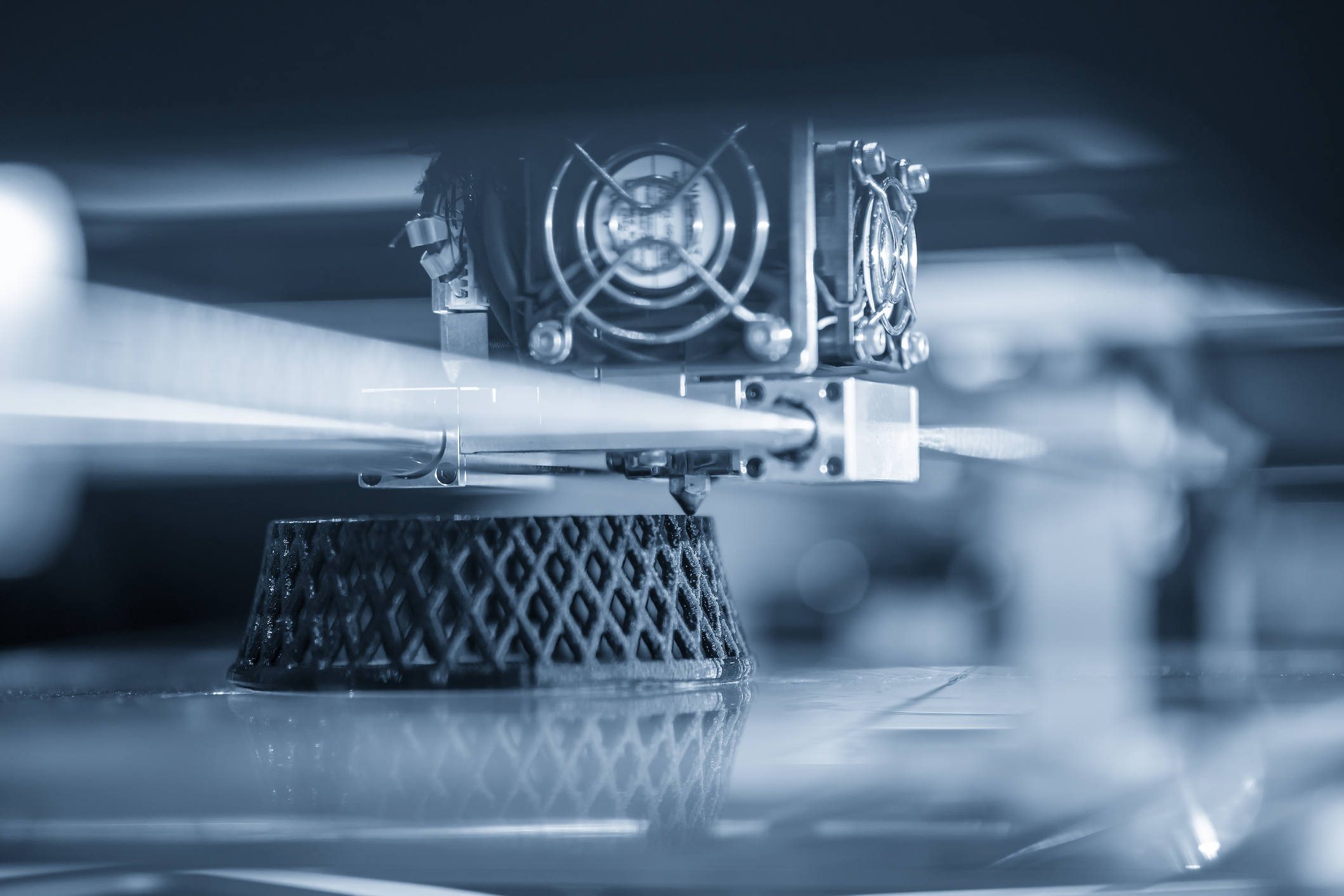
Binder jetting is an additive manufacturing process that selectively deposits a liquid binder onto a bed of powder. The binder holds particles together to form a green part, which must then undergo the post-processing appropriate to the material and application.
It is distinct from both material jetting and selective laser sintering (SLS). The printhead deposits binder rather than the bulk build material, and it does not use a laser to fuse the powder during printing.
The following overview examines its operating principle, materials and potential advantages, alongside the process controls needed to obtain usable parts.
How binder jet 3D printing works

A typical system includes a powder supply, a recoating mechanism, a build platform and a binder printhead. The recoater spreads a controlled powder layer before binder is deposited in the areas defined by the digital model.
The absence of laser melting during printing does not mean that the entire manufacturing route is heat-free. Drying or curing may be required, while metal parts commonly undergo debinding and sintering after printing.
Binder joins the selected particles to create one cross-section of the green part; it does not fuse the whole powder layer. The platform then moves by the layer increment and the sequence repeats.
Loose powder surrounds and supports the geometry during printing. After the required curing or drying, the part is extracted and depowdered. Handling must account for the limited strength of the green part.
Materials used for BJ 3D printing

Unbound powder can often be recovered for reuse, subject to the process requirements. Contamination, particle properties and the supplier’s reuse procedures must be checked; complete recovery and unlimited reuse cannot be assumed.
Feedstocks include metal, sand and ceramic powders. The powder, binder and post-processing route must be selected together for the intended application; the same printer and binder cannot be assumed to suit every material.
Sand binder jetting is used to make foundry moulds and cores. This application is different from printing colour presentation models or producing metal components, which use their own material systems and finishing routes.
Potential advantages and practical limitations
Colour models require a dedicated material system
Some binder-based systems produce colour models using a white composite powder and coloured binders, as in 3D Systems’ ColorJet Printing workflow. This capability should not be generalised to every sand or metal binder-jetting system, nor treated as a universal guarantee of lower cost.
Shrinkage and distortion must be managed
Avoiding a local melt pool during printing changes the thermal conditions compared with fusion-based processes. It does not eliminate dimensional errors or distortion throughout the manufacturing route. Material extrusion, unlike the original comparison in this article, does normally involve heating the feedstock.
For metal binder jetting, densification during sintering can cause substantial shrinkage. The design, green density, furnace cycle and any supporting fixtures must account for it. ExOne’s process overview separates printing from curing, depowdering, debinding and sintering.
Evaluate the complete production cost
Recovering suitable unused powder can reduce material consumption. The saving depends on the fraction actually recovered and qualified for reuse, together with handling and quality-control costs.
A cost comparison must include machine utilisation, binder and powder, labour, furnace cycles, finishing and rejected parts. There is no single powder-reuse percentage or cost ranking that applies to every SLS and binder-jetting application.
Printing speed is only one part of throughput
The surrounding powder can support the part during printing, often avoiding attached build supports. Metal parts may still need fixtures during sintering, and depowdering, debinding, heat treatment or finishing can be significant production steps.
Binder jetting can therefore be attractive for suitable production volumes, but throughput must be assessed across the complete process chain. A faster print cycle is useful only if the finished parts meet the required quality and repeatability.
How speed affects density and surface quality
A 2019 study by K. Myers and colleagues examined how powder-spreading speed affects binder-jetted 316L stainless-steel specimens. It also considered layer thickness, droplet size and specimen orientation.
The study distinguishes powder spreading from binder deposition. Both contribute to layer time, along with powder dispensing and binder drying; printhead travel speed alone does not describe the whole cycle.
Faster spreading generally increased variability in green density and tended to increase surface roughness. Mean green density did not change in the same way for both parameter combinations. After sintering, the trial averages reached at least 97.5% of theoretical density. These findings concern the tested system and specimens, not every binder-jetting process.
Finishing may improve a surface, but it cannot be assumed to correct internal density variations. Production settings must balance throughput with dimensional accuracy, density and the required surface condition.
Conclusion
Binder jetting offers a useful route for selected applications. Its success depends on suitable 3D modelling, controlled powder and binder behaviour, and a validated post-processing chain. These requirements matter as much as the speed of the printer.
Images via dreamstime – This article has been written by John Victor.
THE 3D ADEPT WEEKLY NEWSLETTER
The industry moves fast. Stay ahead.
Every week, the latest additive manufacturing news, in-depth features and real-world applications, straight to your inbox. Plus, be the first to know when a new issue of 3D ADEPT Mag is out.
Free · One email a week · Unsubscribe anytime
Clicking loads our email provider’s sign-up form, including its analytics and Google’s anti-bot protection. You’re only subscribed if you complete the sign-up. Read our privacy policy.