

We’ve often preached the benefits of DfAM (Design for Additive Manufacturing) in terms of lightweighting, topology optimization, and part consolidation —but one critical aspect tends to be overlooked: designing for depowdering. And that oversight can cause your build to fail. Why is it overlooked, and most importantly, how can one design for depowdering? Our conversation with Solukon and the Exploration Company sheds light on the full view of this step and how, with the right approach, one can optimize 3D printed parts from the start.
There is no debate on the fact that designing for AM is not just about making a part printable. One key takeaway from the many use cases we’ve covered through our online media is that DfAM helps tap into the potential of AM while avoiding design choices that can cause printing problems, higher costs, or post-processing headaches. The fact is, most of the time, key elements of DfAM related to post-processing problems are often linked to support and orientation considerations—the ultimate goal being to minimize the need for support structures, which can affect surface finish.
This may further underscore the fact that post-processing challenges – depowdering in particular- are considered modest priorities by industrials. Another reason that may explain the fact that designing for depowdering is often overlooked, is the number of misconceptions among part designers about what makes a part “easy to depowder” in additive manufacturing (particularly in powder bed fusion technologies like SLS or SLM).
Common misconceptions among part designers about what makes a part “easy to depowder”
According to Andreas Hartmann, CEO and cofounder of automated depowdering machine manufacturer Solukon, there are two key misconceptions about what makes a part easy to depowder. We summarize them as follows:
- If I can see it, I can clean it
- All internal channels are the same
Hartmann explains:
“Generally speaking, powder removal is still often underestimated when planning an additive production line. Material selection, printing parameters, and thermal properties of the component, among other things, are all things that initially take priority in the process.

Also, with regards to what makes a part “easy to depowder” there are some misconceptions. Because there are even geometries that look simple and still cannot be depowdered completely by only rotating the part. A classic example of such a geometry is a sugar shaker. No matter how you move it, a few grains of sugar remain at the end.
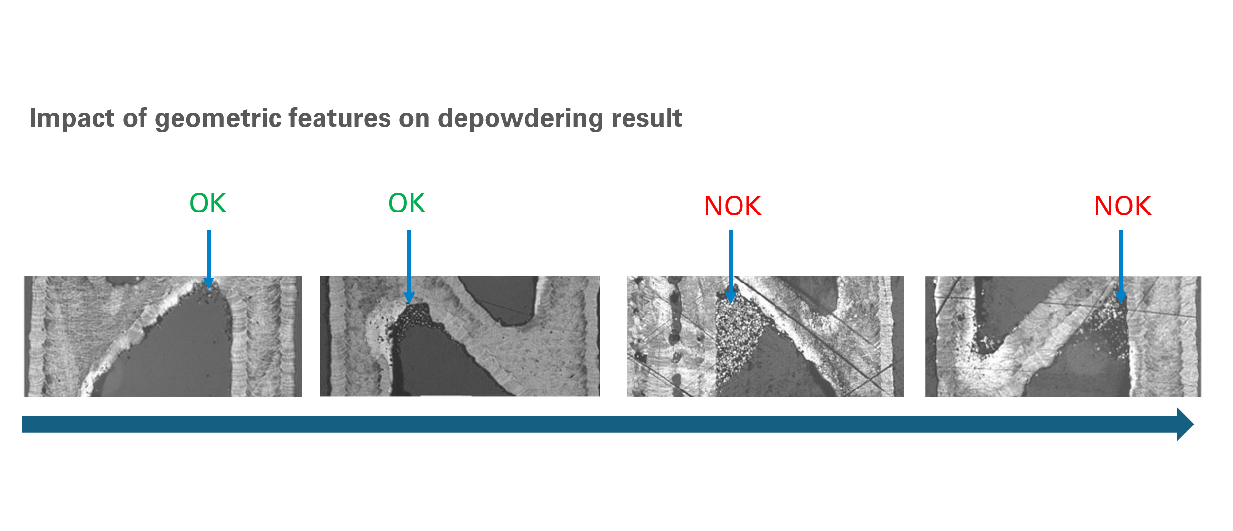
Another problem is when channel openings are not accessible. Often, some of the channel openings are covered by the build plate or tight support structures. Also, designers sometimes overlook that the geometry of the channels also matters in cross-section. For example, a channel with a triangular cross-section requires a certain minimum diameter so that the powder can flow “around the corner”. If the channel cross section is not round but angular and its radius is too small in the corners, the powder can get stuck in these corners. The component then looks simply structured from the outside, but the structure in the cross-section makes it a challenge to remove the powder.”
To those two misconceptions, one can add the fact that a lot of part designers often think that orientation alone will solve depowdering issues. Indeed, orientation during printing helps, but it’s not a silver bullet. This may emphasize the need for looking at ways to optimize 3D printed parts during the design stage.
Optimizing 3D printed parts during the design stage: what features influence the success and efficiency of the depowdering process?
To depowder a 3D printed part, the designer might want to place a focus on part orientation, the behavior of powder flow, internal channels, thermal effects, etc. However, regardless of the depowdering technique used, one key principle remains: every application is different. That means geometry, material structure, and part complexity must all be assessed individually to achieve the best depowdering results.
Speaking of those critical design features that influence the success and efficiency of the depowdering process, Hartmann outlines:

“The smallest channel diameters of the component are crucial. From 1 mm upwards is ideal. Below this, it depends on the shape and arrangement of the channels and on the powder material whether the smallest diameter can still be depowdered. We have already depowdered channels with a diameter of 0.4 mm in our systems and our team always achieves the maximum possible result.
Narrow, tortuous, or blind geometries can make depowdering extremely difficult, if not impossible. Another important factor is surface roughness. Excessively rough surfaces can cause powder to stick through mechanical interlocking, complicating cleanup even further.
In order to be sure that a part can be depowdered, it’s good to keep the length-diameter ratio of the channels in mind. A value of 4 is ideal for depowdering, but of course, we have experienced that many complicated build jobs like heat exchangers fall below this value.”
According to The Exploration Company (TEC), a European aerospace company that develops reusable spacecraft and space logistics solutions, they assess parts for “depowderability” during the design phase.
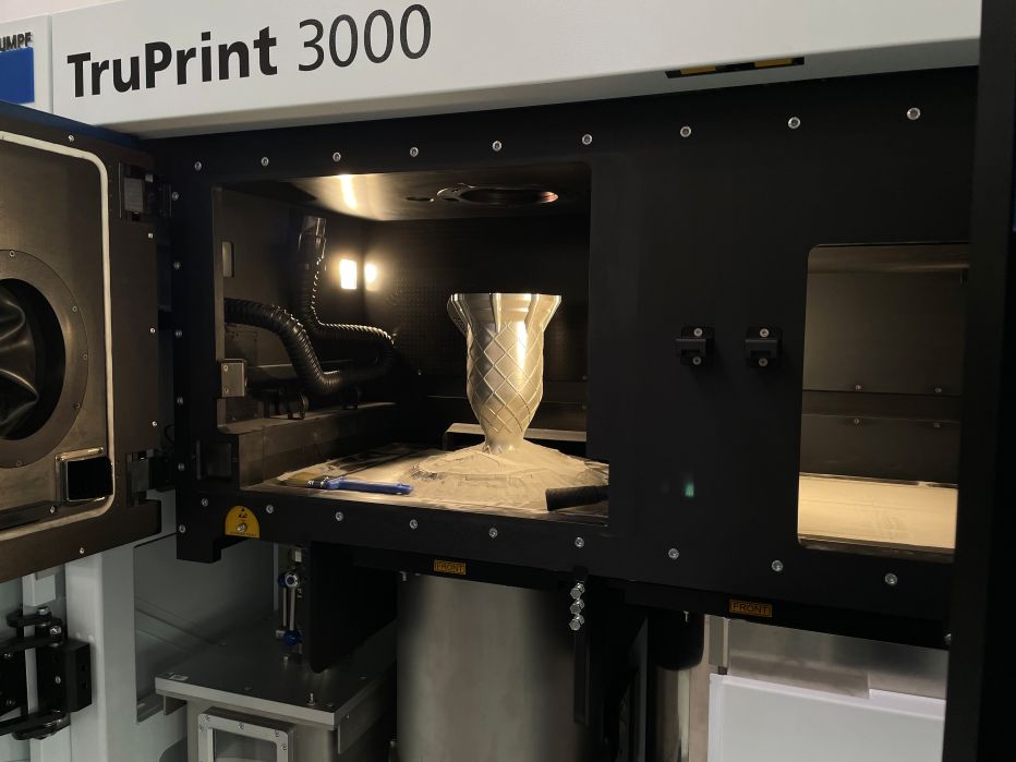
For the record, with the need for fast iterations and short turnaround times to maintain full control over design and production, the team at The Exploration Company decided to bring AM in-house, accelerating this way their production from design to finished product in weeks rather than months. Key equipment in the company’s production includes the TruPrint 3000 LPBF system, which uses lasers to selectively melt thin layers of powder, and the Solukon SFM AT350-E—the first depowdering system with ultrasonic excitation. Moving forward, the company plans to integrate an in-house heat treatment solution, which is currently outsourced. Once heat treatment is complete, the parts are cut from the build plate using Wire Electrical Discharge Machining (WEDM), followed by final machining of flanges and interfaces for the test bench.
Speaking of their depowdering process, Maxi Strixner, Senior Additive Manufacturing Engineer at the Exploration Company, explains:
“Depowdering feasibility is assessed from the very first design review. If we identify features that could hinder complete depowdering, they’re flagged during the Design for Additive Manufacturing (DfAM) phase and revisited in future design iterations. Part orientation is typically determined by our AM team, drawing on years of experience manufacturing aerospace components. That expertise guides decisions around orientation, striking the right balance between print quality, depowdering, and post-processing. In fact, the initial orientation plays a major role in how we design parts for depowderability.”
Strixner said that this assessment from the design phase helps mitigate the remaining risk, thanks to the Solukon SPR-Pathfinder® software. But as Hartmann points out, there’s a lot more this software can do—especially when used early in the design process.
The SPR-Pathfinder® software: how can we predict depowdering challenges at the design stage?
The focus on SPR-Pathfinder® serves as a powerful reminder: overcoming depowdering challenges isn’t just about hardware. A machine’s ability to deliver automated, repeatable results depends heavily on the software it runs. Solukon has highlighted this key message since 2022, when it became the exclusive licensee of the SPR-Pathfinder® technology.
According to Hartmann, the ability to help engineers predict depowdering challenges at the design stage, is what makes the software so useful for the production process. He notes:
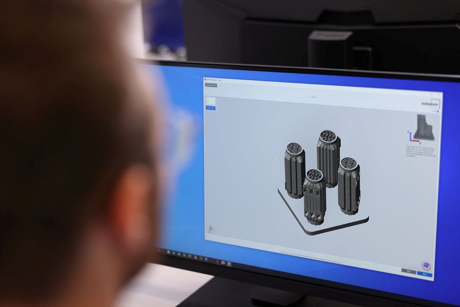
“You load the CAD file of the part into the software, define the minimum particle feature size and the material, and the software then calculates a part-specific cleaning program. It even works for multiple components on a single build plate, treating them as one part.
The algorithm simulates how fluidized powder behaves under gravity, calculating an exit route—much like designing emergency evacuation routes in a building or stadium, where you want to avoid overcrowding or blockages at the exits. It identifies where powder can flow and generates pathways for it to escape from internal areas.
Sometimes, Pathfinder might indicate that complete powder removal isn’t possible, especially for parts with very intricate internal geometries, like a heat exchanger where the channel diameter or outlet is too small. In those cases, the software shows exactly where the bottleneck occurs and where powder is likely to get trapped. That’s why we recommend running Pathfinder before printing. If you discover after printing that powder can’t be removed, the part might be invalid, or at the very least, the functionality of an internal channel could be compromised.
It makes sense to use Pathfinder even before the design is finalized. For complex components, this kind of inspection in the design phase is essential, because no human can assess every internal pathway at once. It’s like solving a Rubik’s cube: you think one side is perfect, but another side is completely wrong, full of powder again.
Take a transparent heat exchanger, for example. No one can truly predict how powder will behave in every single channel. That’s where the algorithm excels. It checks its calculated movements over and over through simulation, ultimately providing a result with 100% accuracy.”
The case of the main combustion chamber
 In the range of applications they have already achieved with AM, Strixner identified the Huracan’s main combustion chamber as one that particularly demonstrates the capabilities of the SPR-Pathfinder® software. The “Huracan” engine is a liquid propulsion methalox (liquid methane as fuel and liquid oxygen as oxidizer) engine for lunar missions.
This application reveals how the Exploration Company’s team considered part orientation, the behavior of powder flow, internal channels, and thermal effects as key design features to ensure the success of depowdering.
“A particularly impactful case was the main combustion chamber used in the Pathfinder demonstrator engine. This component features intricate internal regenerative cooling channels, which are essential for maintaining thermal performance but extremely challenging to depowder due to their small diameter and tortuous path. Without proper orientation and analysis, these channels risked incomplete depowdering, which would compromise not only the part quality (due to trapped powder causing blockages or contamination during hot-fire) but also the post-processing efficiency, as residual powder can be released unpredictably during WEDM or machining,” Strixner continues.
By integrating SPR-Pathfinder® early in the DfAM phase, the team identified several critical areas prone to powder stagnation. They implemented design modifications, such as adding venting features and adjusting channel curvature, to improve powder flow. As a result, the chamber was successfully depowdered on the first attempt, saving an estimated 3–4 days of rework and cleaning, and eliminating the risk of internal contamination that could have caused test failure.
“The SPR-Pathfinder® software has been instrumental in validating our design choices. While years of experience guide our initial design and orientation, it provides visual confirmation and verifies powder flow behavior, reducing uncertainty and optimizing post-processing time. It thus played a vital role in de-risking production and ensuring the repeatability of AM processes for mission-critical hardware,” Strixner points out.
Concluding notes
Designing for depowdering matters, to reduce post-processing time and cost, prevent part defects, and enable the use of complex internal geometries safely. Although this was not mentioned in the article, meeting these points ultimately helps to ensure regulatory compliance, especially in critical sectors such as aerospace.
The example of The Exploration Company highlights how design modifications, such as adding venting features and adjusting channel curvature, can improve overall powder flow. However, as Solukon’s CEO points out, other applications show that changes to lengths, curve radii, or the component’s position on the build plate, based on Pathfinder’s calculations, can also enhance the depowdering process.
“We are still at the beginning of a process in terms of awareness of the importance of software. This shift in mindset to consider depowdering in the design process is one of our main concerns. More and more customers are benefiting from this, so that it will become established across the board over time. The simulation of self-programmed processes is pointless, and manual programming is no longer able to cope with the increasing complexity of the components in the long term anyway. This will automatically lead to the need for automated simulation of the depowdering process being recognized across the board as early as the design phase,” Hartmann concludes.
Editor’s notes
Gathering Hartmann and Strixner’s perspectives offer valuable insight into how Solukon’s technology is being leveraged—and how much potential remains for further optimization.
This content has been created in collaboration with Solukon and The Exploration Company. Read all news about Solukon here.


