

Key facts regarding the most complicated 3D printed parts installed on XB-1
When Boom Supersonic announced in 2019 that it would 3D print hundreds of parts for its supersonic demonstrator aircraft, it was clear that additive manufacturing (AM) would be a cornerstone of next-generation supersonic flight. The only question was: to what extent? From technology integration to material qualification under extreme conditions and key applications, Ruslan Pshichenko, Manufacturing & Additive Engineer and leader of AM efforts at Boom, shares key milestones and lessons from the company’s AM journey.
Founded in 2014, Boom Supersonic began using additive manufacturing (AM) in mid-2017, when it partnered with Stratasys to support the development of its XB-1 demonstrator aircraft. This marked its transition from traditional methods to rapid, on-site prototyping and tooling. Two years later, the company expanded its use of AM with Velo3D’s metal AM technology and started exploring the production of metal flight-grade 3D printed parts.
Today, in addition to various Stratasys 3D printers, the company integrates an EOS M 400-4 metal 3D printer to ensure the production of high-performance components for the Symphony prototype engine core. These parts include, for example, blades, vanes, and blade seals.
As Pshichenko shares these examples of applications, we can’t help but realize that the aerospace industry has glamorized the use of AM for critical parts in advanced applications.
One reason that may explain this is that aerospace companies can often showcase 3D printed parts on demonstrators, highlighting their technological leadership. However, for various reasons, these parts may not make it into final production aircraft.
The “marketing appeal” of such headlines aside, we tend to forget that complex doesn’t always mean better. AM may enable complex geometries, but complexity can introduce new failure modes.
So, how does Boom de-risk additive manufacturing?
The short answer is through non-critical parts. Boom’s use of AM on XB-1 shows that the use of AM for producing non-critical parts helped validate the technology and support its adoption for future critical applications.

“On XB-1, most of the 3D-printed components were structurally non-critical. Examples include hydraulic line blocks, throttle cable support brackets, and enclosures for printed circuit boards, all made with ULTEM 9085CG and used in lower-load environments.
By initially applying AM to less critical parts, we’re able to accelerate our learning while minimizing risk. These parts offered valuable lessons, from design iteration to manufacturing process control, at a lower cost and with lower risk compared to critical components. This incremental approach builds confidence, both in the team and in the technology, paving the way for its eventual use in more demanding applications,” Pshichenko explains.
Looking at the various high-performance 3D printers the company has in its production facility, the engineer outlines how each of them helped to meet specific production requirements:
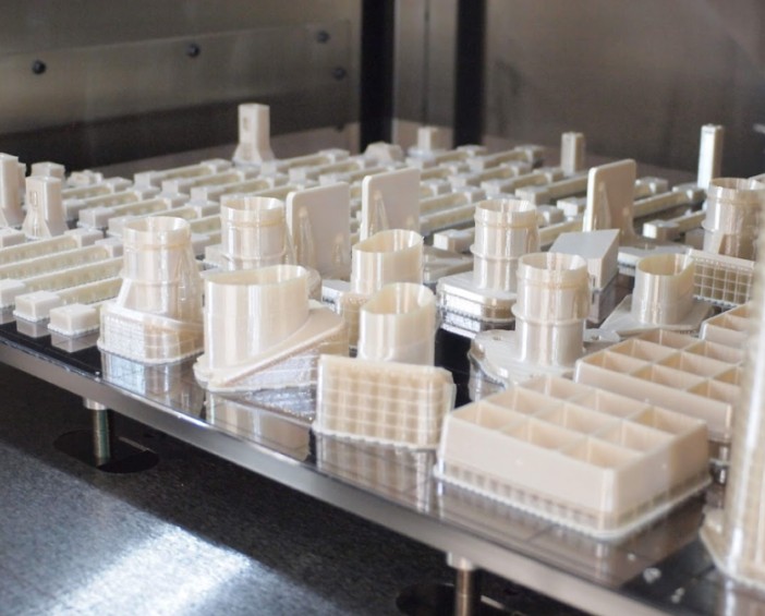
“The Stratasys F900, for instance, played a central role in printing all the flight hardware for XB-1 and helped produce over 350 parts flying supersonic using ULTEM 9085CG.
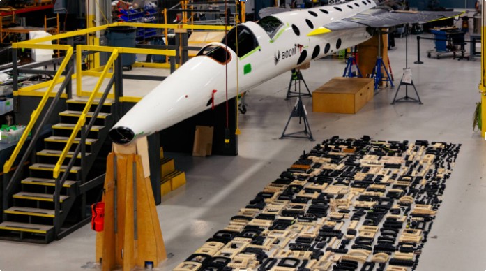
It also supported extensive tooling efforts, producing around 750 drill guides used to drill more than 10,000 fastener holes across the aircraft, primarily through stackups of carbon fiber, titanium, and aluminum.
The Stratasys 450mc 3D printer is primarily used for tooling and large functional prototypes, such as clearance checks and kinematic mechanisms. It prints with Nylon 12CF, an ideal material for applications requiring high strength.
And the Stratasys F370 is essential during the early stages of design development. It enables fast iteration using ASA material, which offers a good balance of strength, aesthetics, and durability.”
These examples of Boom’s engineer reveal how non-critical 3D printed parts exposed the technology to actual flight conditions —vibration, thermal cycles, pressure, and wear, while validating digital thread and production consistency. Additionally, since regulatory agencies (e.g., FAA, EASA) require evidence of material behavior, process control, and part performance before approving flight-critical applications, starting with non-critical parts shortens the approval cycles and offers a low-risk way to engage with regulators and iterate standards.
“At Boom Supersonic, we’ve found that non-critical parts across nearly every system on XB-1 are ideal candidates for additive manufacturing.
The most prominent example is the Hydraulic System, where we printed around 100 line blocks using ULTEM 9085CG. Given the volume and unique geometry of each block, additive manufacturing proved to be the most cost-effective and efficient solution.
Other systems, such as the Electrical Power System (EPS), Environmental Control System (ECS), Flight Controls, and Fuel System, also benefited significantly from AM. These components often required lightweight structures, rapid turnaround, and design flexibility, all of which are areas where additive manufacturing excels.
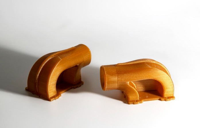
A particularly impactful application was the air ducts within the ECS. Each duct was uniquely shaped and featured complex internal geometry optimized for airflow. Additive manufacturing enabled us to rapidly design, test, and iterate these components, turning early concepts into flight-ready hardware with unmatched speed and adaptability,” the subject matter expert adds.
Supersonic flight’s extreme conditions and what it means for AM
Supersonic speeds, defined as speeds exceeding Mach 1 (approximately 767 miles per hour or 1,235 kilometers per hour), can dramatically reduce passenger travel time. To give you an idea, a flight from Los Angeles to Tokyo, which normally takes about 11 hours, could be shortened to just six hours or less, thanks to supersonic travel.
These conditions are a stress test for aerospace manufacturers looking to use AM, as they need to address several challenges, including, for instance:
- High temperatures and thermal gradients: this means AM must produce heat-resistant, thermally stable parts
- Shock waves and pressure loads: this means components must withstand sudden pressure spikes, especially around inlets, ducts, and control surfaces. Additionally, geometry must be precise to manage airflow
- High structural loads at low weight; vibration and fatigue loads: this means that 3D printed parts, especially load-bearing ones, must resist cyclic stress and fatigue cracking. They must also combine mechanical strength with weight efficiency
- System integration and size constraints: In tightly packed systems (avionics bays, air ducts), available space is limited. Therefore, parts must be compact, modular, and easy to fit.
- Environmental compliance: Low-boom shaping and efficient combustion systems require fine-grained geometric control and rapid iteration during R&D.
“Many of the 3D-printed parts installed on XB-1 were located in pressurized zones, such as the cockpit, or in more thermally stable areas like the systems bay, which houses most of the electrical, ECS, and flight controls equipment.
Additive manufacturing was also used in more exposed areas, including the nose and main landing gear bays. In these zones, components had to withstand challenging conditions such as:
- Elevated temperatures during flight at altitudes up to 35,290 feet and speeds of Mach 1.122
- High-speed airflow during takeoff and landing when the gear doors are open and the aircraft reaches speeds of up to 160 knots
To ensure part performance, the engineering team carefully reviewed the datasheet for each AM material, in this case, ULTEM 9085CG, and verified that the expected in-service loads remained within the published material allowables. In addition to relying on supplier data, Boom conducted its own internal material qualification to validate key properties.
As part of our quality assurance process, the Stratasys F900 machine underwent a full inspection every three months. This included printing and testing 30 dogbone specimens (15 in the XZ orientation and 15 in ZX) which were pulled to failure on a load frame. These tests helped confirm that the printed material consistently met mechanical property expectations and remained within spec over time,” Pshichenko explains.
 To rapidly iterate and test engine designs that would otherwise be constrained by traditional manufacturing timelines, the company is currently using Haynes 282. This high-strength, heat-resistant superalloy has helped print over 200 components for the turbine section of the prototype engine for Symphony. It was selected for its excellent mechanical properties at elevated temperatures, specifically designed for structural applications exceeding 1,500°F, such as those found in jet engine environments.
Speaking of high structural loads, the engineer confirms that for XB-1, most of the 3D-printed components were used in lower-load applications. For the engineering team, direct structural weight savings weren’t the primary focus.
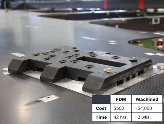
“One notable example is our use of AM for drill blocks. XB-1 contains over 10,000 fastener holes, many of which pass through complex stackups of thick titanium and carbon fiber. Given the uniquely contoured outer mold line (OML), we needed highly customized drill guides to ensure accurate hole placement during assembly.
Additive manufacturing allowed us to rapidly produce these drill blocks in a cost-effective way. The images below illustrate both the volume of blocks produced and the cost and time savings per part. The pictured drill block is just one of many that supported precision drilling in areas such as the wing skins, ultimately enabling faster assembly without compromising quality or positional accuracy,” Pshichenko points out.
Key facts regarding the most complicated 3D printed parts installed on XB-1
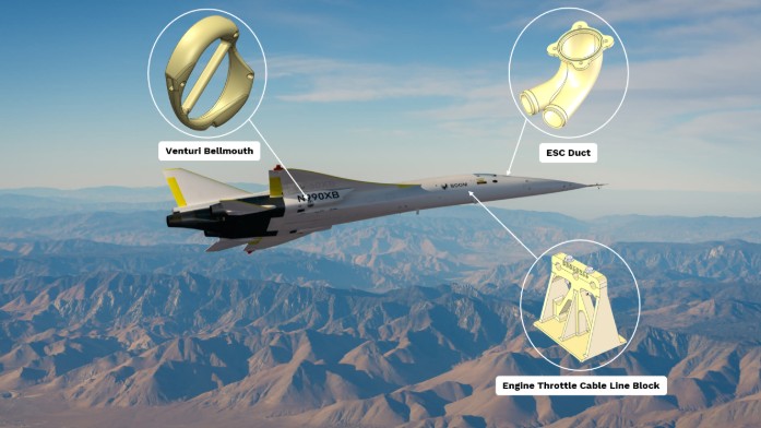
According to Pshichenko, several 3D-printed components on XB-1 were complex in different ways, but a few stand out due to their geometry, function, and integration challenges:
- ECS Duct: This part was designed to direct cooling air to instruments and avionics located forward of the cockpit panel. It features intricate internal geometry optimized for smooth airflow, something that would have been extremely difficult, time-consuming, and costly to produce using traditional manufacturing. Fortunately, our Stratasys F900 handled the complexity with ease, allowing us to go from design to installation rapidly.
- Engine Throttle Cable Line Block: While not as geometrically complex as the ECS duct, this part played a critical and functional role. It supported all three engine throttle cables as they passed through the aft cockpit. The block was bonded directly to the carbon fiber keel beam and clamped the cables between upper and lower sections using fasteners. You can see the three distinct holes for cable routing in the image below, precise placement was essential to ensure safe and reliable operation.
- Venturi Bellmouth: This component also featured highly complex internal geometry, designed to channel airflow efficiently through a check valve and into the engine bay. Its purpose was to help cool the area, especially during full afterburner operation. Like the ECS duct, this part would have been prohibitively difficult to fabricate conventionally, making AM the ideal solution.
Each of these parts highlights a different advantage of additive manufacturing, whether it’s geometric freedom, functional integration, or rapid development for specialized use cases.
Broader integration of AM at Boom
The supersonic demonstrator was a testament to what AM can do to bring back supersonic commercial flight. Overture, the ultimate goal of this mission, is designed to carry 64–80 passengers at Mach 1.7. While we don’t know yet exactly how AM will be used in this commercial supersonic airliner, all eyes are now turned toward Symphony™, the engine that will power Overture.
The company recently shared that the engineering team will be using AM to rapidly prototype metallic components in the heart of Sprint Core, its test article for Symphony.
This test article is said to include the high-pressure compressor, the combustor, and the high-pressure turbine (essentially the engine’s “hot” section). The company is currently printing 193 parts in total – all of them will be fully operational and critical to validating the core architecture.
“As we look to the future, Overture will certainly incorporate both metallic and thermoplastic 3D-printed parts. That said, we’re taking a measured and strategic approach, extensively testing and validating where additive manufacturing makes the most sense before integrating it into commercial production. Additive manufacturing isn’t a one-size-fits-all solution. While it has clear limitations, it also offers significant advantages in the right applications, particularly where traditional manufacturing would lead to heavier, more expensive, or more complex parts. Scaling AM for Overture will involve a robust effort around material testing, process validation, and certification to meet stringent commercial aerospace standards. We’re committed to doing that work, because when used correctly, additive manufacturing can deliver real value in terms of performance, efficiency, and sustainability,” Pshichenko concludes.
All images: courtesy of Boom Supersonic. This interview has first been shared in the 2025 May/June edition of 3D ADEPT Mag. Discover the entire issue here.


