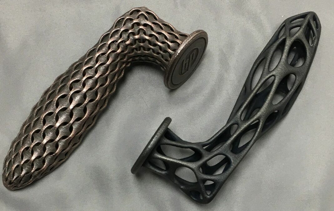
Like a wide range of post-processing tasks used for 3D printed parts, electroplating aims to enhance the physical properties of the part through increased wear resistance, corrosion protection or aesthetic appeal, as well as increased thickness. Here is the thing, very few people in the industry know exactly what the process is, how it works and how it can be applied to AM parts. Unlocking the mystery around this concept is what this article ambitions to achieve.
Also known as electrodeposition or electrochemical deposition, electroplating is an electrochemical surface coating process that uses an electric current to reduce dissolved metal cations on an electrode surface, called a cathode, forming a thin coherent metal coating. In other words, through this process, one can reduce metal ions onto the surface of a conductive part to apply a metal coating.
There are quite a few metals that can be electroplated but some of the most commonly used are copper, nickel, chrome, tin, lead, zinc, brass (an alloy of Cu and Zn), gold, silver and platinum. Put simply, the process aims to serve two main purposes: decorative and functional.
For instance, decorative electroplating is often seen in the automotive industry, where a decorative chrome coating can be recognized on plastic elements such as grilles, bumpers, wheel rims or door handles. One can also use decorative plating for the deposition of precious metals (for instance, gold and silver) on luxury items, and here you might think of watches, or jewelry in general. Furthermore, most people use electroplating to make their plastic parts attractive like polished metal pieces.
The functional electroplating process aims at achieving a metal coating that will, among other properties, prevent the target substrate materials from corrosion. In the aircraft industry for example, where common metals to be plated are cadmium, hard chrome, zinc, zinc-nickel, platinum, tin-zinc, etc., a few examples of parts that can be electroplated include landing gears, engine turbines, or bearings.
This functional purpose can also involve several other goals: the need for increasing temperature capability of the print, EMI shielding, improved mechanical properties (stiffness and strength), better durability, barrier coating to stop outgassing (i.e. a vacuum environment) or prevent attack of chemicals on printed resins substrates. It can also reduce flammability and toxic fumes from combustion. This means that a 3D-printed part that underwent electroplating can also serve as a replacement part for a given component that had a specific function in an assembly.
In the post-processing of 3D printed parts, electroplating is just one way of surface finishing like 3D printing is just one manufacturing tool. To successfully obtain a metal coating on a 3D printed part by the electroplating process, one needs to recognize what type of substrate material we deal with, whether this is a plastic part, or a metal-based part, and the function of the deposited metal layer, decorative or functional, and we are ready to go.
With what 3D printing technology can we use electroplating?
In general, the 3D printing technology used for part manufacturing does not really impact the electroplating task. However, one tends to realize that photopolymer, fused/sintered powder or filament 3D printed parts can be plated. The easiest to plate are photopolymer but the parts need to be cleaned and well cured. The complexity with fused/sintered parts is that they can have a bit of porosity and the surfaces can be rough. Most 3D printers can be set up to make the outer skin of the part watertight but there can be some variability in batches. The surface roughness can improve adhesion but it’s more difficult to get a high gloss finish with these. FDM remains the most difficult process when it comes to electroplating because there is almost always porosity in the part and the pore sizes in certain regions of the parts can be quite large. Parts need to be sealed prior to plating which adds to the cost to process these.
That being said, regardless of the AM process used for the manufacture of 3D printed parts, what really matters are the substrate material this part is made of and its geometry: metallic parts barely raise issues compared to plastic parts that require the operator to ensure that the material used for the manufacturing, can withstand the chemical bath that will be used for the electroplating process.
Furthermore, the more complex the geometry of the part, the greater the non-uniformity of the deposited metal on its surface. This makes the electroplating process challenging for the process control, and achieving an even metal layer coating distribution over all active surfaces to be plated might not be possible without developing dedicated mitigation strategies.
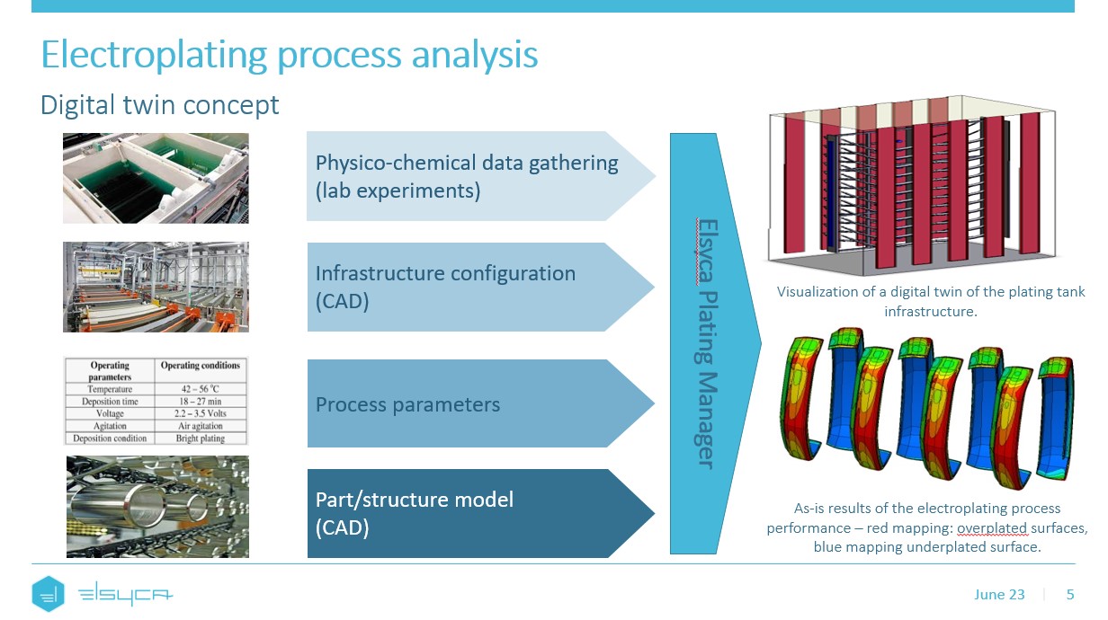
Since 3D printed parts are usually complex ones, it is often recommended to use a computer-aided engineering approach in electroplating. Such an approach aims to ensure upfront process analysis towards recognition of under- and over-plated surface areas. This way, one could predict the metal layer thickness distribution over 3D printed part before the actual electroplating process will be run. This, in turn, gives the operator the possibility to optimize the process setting and make sure the part is plated right-first-time and is compliant with required metal layer thickness specifications.
How to apply electroplating on 3D printed parts?
Plating onto 3D printed parts is rather similar to the electroplating processes done for typical plastic or metallic parts. One needs to start with uncontaminated parts, then etch the surface, apply a conductive layer with autocatalytic nickel or copper, then apply plating sequence to achieve desired functionality.
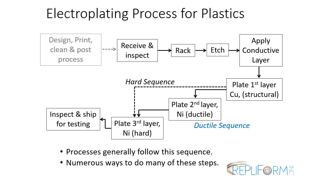 Moreover, for plastic 3D printed parts, it’s important to make sure that the part is metalized beforehand so that the surface can conduct the current. As shown in the image above, this metalization step is usually done with an electroless deposition and after the proper surface preparation, composed of a number of pre-processing steps: cleaning, pre-dipping, etching, neutralizing, pre-activating, activating, and accelerating. Once the surface pre-processing is done, one can proceed with the electroplating step.
Determining how electroplating alters mechanical properties of 3D printed parts
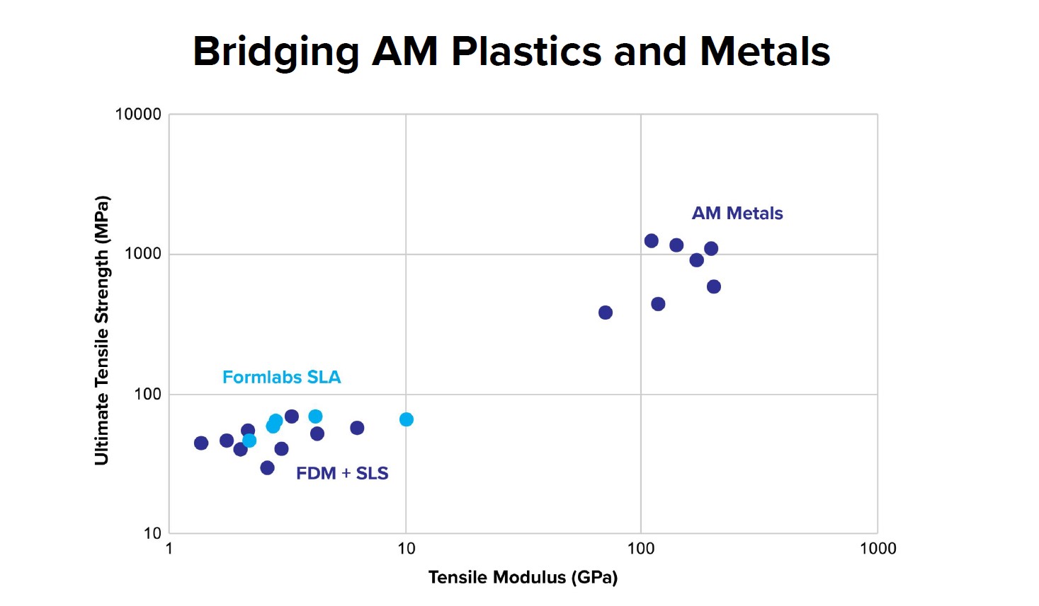
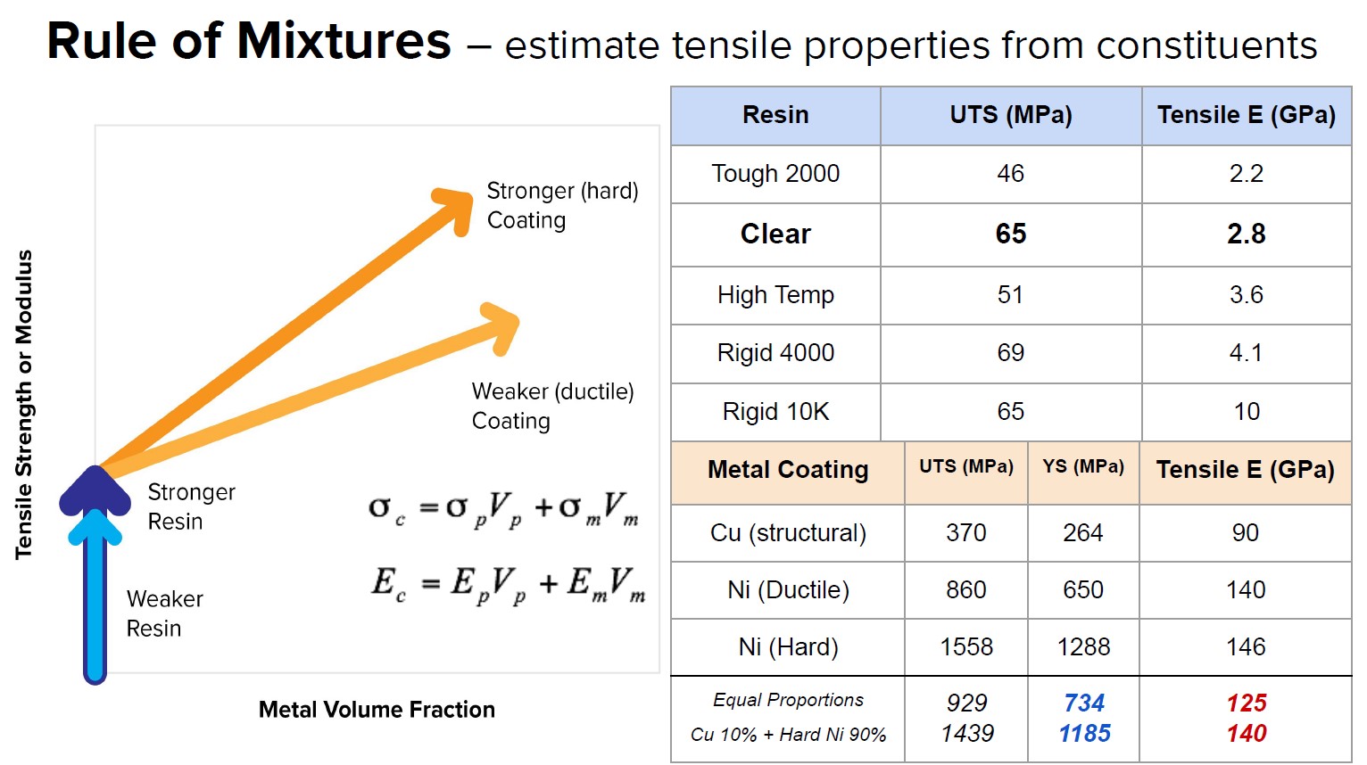
On another note, determining how electroplating alters the mechanical properties of 3D printed parts requires developing an understanding of several mechanics. Electroplating on 3D printed plastics, for instance, can make a reinforced composite and add metal functionality to non-conductive metals. To create a metal-resin composite from SLA and electroplating for instance, one should determine if a plated plastic can fill a gap between printed metal and plastics, one should understand the rule of mixtures to estimate tensile properties from constituents or learn to make room for the coating when you already have the design.
To understand this type of mechanics and many others, companies like RePliForm Inc. work with many systems suppliers and resin manufacturers to test tensile and flexural strength. Indeed, as the properties of the resin change, the properties of the coating change as well, and this influences the way the part design changes.
That being said, as far as the creation of a metal-resin composite is concerned, it turns out that treating the plated part as a composite and using the rule of mixtures – a very basic equation used to estimate the strength of composite parts – works surprisingly well.
 Improving electroplating via a Computer-Aided Engineering approach
Enhancing electroplating via a Computer-Aided Engineering approach is important as we navigate the era of Industry 4.0 and Smart Manufacturing concepts, which 3D printing and digital twin are both parts of.
The approach of a computer-aided engineering relies on the recognition of the electroplating process performance and its further optimization before any actual wet run will happen. This can be done by creating a virtual representation (digital twin) of the actual plating process setup in a computer environment. This digital twin is based on the technical information coming from the real-life process site, taking into account plating line infrastructure, operating parameters of the plating process, electrochemical performance of the plating bath used, geometrical characteristics of the component to be plated, and a specific rack layout we have envisioned.
With this approach, one can predict the current density and metal layer thickness distributions over all active surface areas that have to be plated, recognizing the surface risk issues in terms of over- and under-plating. Once this knowledge is gained, one designs and evaluates an appropriate mitigation strategy, dedicated to the process setup and to the specifics of the part’s geometry.
This is extremely important in the case of geometrically complex parts such as the 3D printed ones, where neither changing the rack layout nor tuning up the process parameters will work in order to achieve an even coating coverage.
For such complex parts, the process setup will need to be improved and a dedicated tooling concept will need to be developed and tested. In real process life, assessing the process risks and sorting out a proper mitigation strategy, including testing, takes months and months of hard work and wasted resources. The approach of computer-aided engineering allows us to do it within a few minutes, eliminating an excess number of wet tests and thus, saving time, money and resources of all kind. Using a computer-aided engineering approach we are improving our process knowledge and gaining control over its performance, assuring the best quality possible, each and every time.
 So…?
So…?
The process of electroplating is definitely a powerful task in post-processing. Although a CAE approach may help speed up the process, it should be noted that it does not seem to have a popular method to automate the process steps. As seen with depowdering, it will take a lot of collaboration between machine and material manufacturers and electroplating experts to advance the process steps and foster its utilization across industrial 3D printing applications.
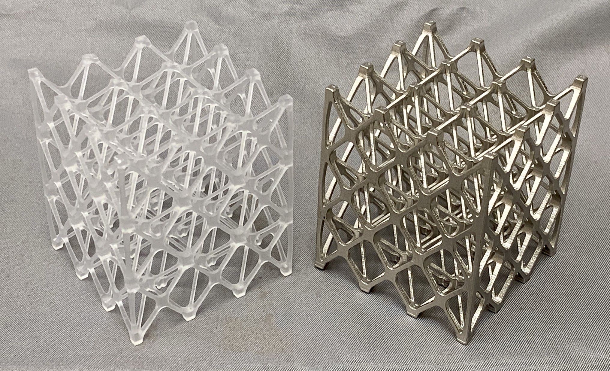
This dossier has first been published in the May/June edition of 3D ADEPT Mag. Featured image: SAMPE Strength Comparison of Topology Optimized Lattice From Printed SLA Resin, Electroplated Resin and PBF Al – Courtesy of RePliForm Inc.
Authors
This exclusive feature has been co-written by Sean Wise, President at RePliForm Inc. and Agnieszka Franczak, Head of Surface Finishing Division at Elsyca N.V..
RePliForm is an expert in the electroplating of 3D printed plastics as well as other non-conductive materials. With the goal of supporting its customers to create a composite part that can expand the envelope of what is possible with a 3D Printed Plastic, RePliForm continuously adapts electroplating processes to a variety of materials and complex geometries. The company recently developed an unexpected way to make a reinforced composite and add metal functionality to non-conductive materials through electroplating of 3D printed plastics. You may reach out to the company here for further information on the topic: info@RePliFormInc.com.
Elsyca is all about electrochemistry and computer-aided engineering solutions. Electroplating, being one of the electrochemical processes, is one of the company’s main interests as it is so broadly used in a variety of applications, across several industries. The team at Elysca develops dedicated software solutions for the electroplating process analysis and optimization and provides computer-aided engineering services for those who face challenges with process control, coating quality and reproducibility. Thus, electroplating of 3D printed parts fits very well in the company’s scope of interests. Elysca recently presented how they help industrials take electroplating processes to the next level via a Computer-Aided Engineering approach. You may reach out to the company here for further information on the topic: info@elsyca.com.


