Finding a design that works first, predicting what’s happening inside the AM machine then.
The last time I was at a trade fair – before the pandemic hit – I stopped at a booth because a beautiful metal 3D printed part caught my eye. I was looking at it without any idea of what it really took to make it when I heard someone behind my back say: “the power of Finite Element Analysis”. I wasn’t sure to understand what it meant. I wasn’t sure either that the editor in me wanted to discuss a very technical topic that would have probably taken a lot of time to understand. So, I smiled, and I laid my eyes on something else.
However, this sentence stayed in my head, and I decided to learn more about it – about Finite Element Analysis aka FEA -. If I should summarize what I learned in one sentence for an end-user, I would say that FEA is probably the ultimate tool that enables to give life to many of the products around us today but this is not a mainstream news magazine, it’s a trade press. Therefore, I believe, you expect me to dig a little deeper and to do so, I invited software provider ANSYS and manufacturing on-demand service Xometry to share their expertise on the topic.
This article aims to:
- Shed light on the main uses of FEA in an additive manufacturing production environment and how theory might differ from its practical aspect;
- Present its advantages and complexities in a given AM process: the specific cases of metal AM and FDM will be taken into account here;
- Provide tips to those who will leverage this tool in their work
Finite Element Analysis: What? Who? Why?
FEA is a process developed as a means to address structural mechanics problems in engineering. Research shows that mathematician Euler was one of the first to leverage the concept in the 16th century but a more understandable definition was found in the works of Schellbach in 1851.

According to Brent Stucker, Distinguished Engineer in Additive Manufacturing at Ansys, decades ago, when engineers discovered the potential of this method in design, to apply it, they had to go through the tedious process of writing equations for each element or a matrix algebra required to obtain the desired solution. The reason was, the method required the engineer to divide a structure into discrete elements which were joined at common points called nodes. Writing equations therefore, helped describe the behaviour of each element, so that the method applies loads and boundary conditions, assembles an overall stiffness matrix and solves the set of resulting simultaneous equations.
With the advancement of software tools, the FEA method is more “automated” today. “The user might not require such calculations because the simulation tools are much more intuitive. They can use machine learning. So a non-expert can still have good results”, Stucker notes.
With the help of computer-based codes, the engineer can generate solid models of a part, discretize the model into elements, apply loads and boundary conditions, and thereafter wait for the computer to perform the analysis and decipher the results.
What?
However, the understanding and the main uses of this method remain quite confusing for most professionals today. For Stucker, professionals should make a clear distinction between two separate uses of FEA, especially when it comes to the AM process:
“It’s essential to distinguish between using FEA for the design of the component and on the other hand, to predict what’s going to happen to that design while it’s being built in the AM process. There are the two separate uses of the FEA process that people sometimes, confuse; and one uses two completely different types of FEA for these two problems.”
This means that the first questions professionals should ask themselves are: am I predicting the design of the part? Or am I predicting what’s happening in the process? Indeed, when FEA is being use for the design of the part, the focus here is on the geometries of the part. In this case, it is important to de-risk and to optimize designs before they go into production, whereas when it is used as a process simulation tool, the focus is on the manufacturing itself, on what’s going on in the physics of the machine, what will happen to the material used in the machine, etc.
By combining these two main uses of FEA, Greg Paulsen, Director of Application Engineering at Xometry explains:
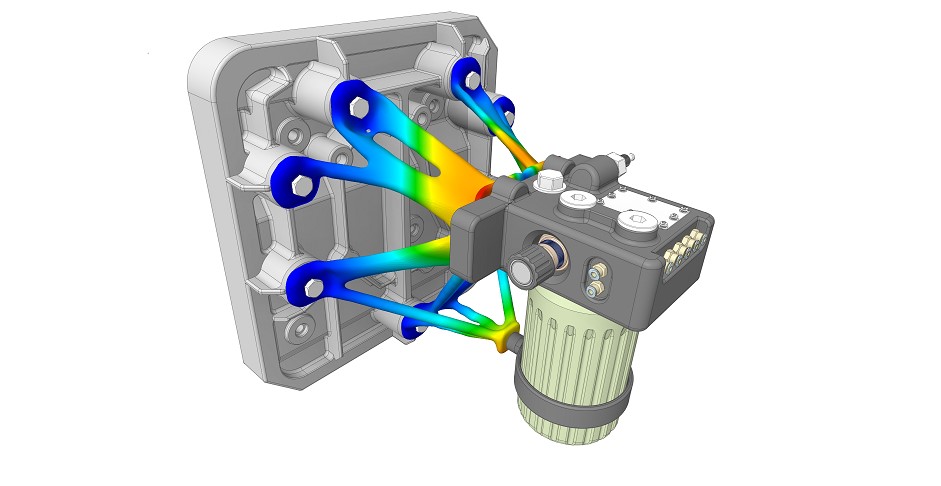
“FEA helps prove out your design will do what you say it will do in a digital space. Finite Element Analysis is a tool to help predict the results of a design’s performance before any physical part gets fabricated. Its advantage is that you can simulate, iterate, and validate your design’s “digital twin” without sinking time and cost into manufacturing and mechanical testing. FEA works by assigning material properties to a 3D model as well as environmental conditions and loads.
The simulation takes all of these into account to predict if those conditions affect the part’s structure integrity, even predicting deformation or critical stress points. Based on FEA feedback, you can modify your design to mitigate these effects or increase a safety factor. Ideally, FEA will help create the intended outcome and performance of your design so that when you build the part, you and your team have data-driven confidence that it will work”.
This is certainly the reason why FEA is seen by most professionals as a costs justification and simulation tool.
Who (can use it) & Why?
Listening to what the FEA method is, might give the illusion that the process is only intended to designers, but Ansys’ Stucker points out that in the end, the “main goals of running FEA depend upon your job description.” In other terms, whether you are a designer, an operator, a material scientist, or a quality engineer, you might find yourself leverage an FEA method in one of your tasks.
“As a designer, it’s for making an optimum design that actually performs as intended. As a machine operator it is to avoid build failure, minimize post-processing costs, maximize machine productivity and achieve part tolerances. As a material scientist it is to ensure the material microstructure is correct, etc. There are many people who can use FEA to make their AM operations better”, Stucker notes.
No matter what your job description is, the expert ensures that “running FEA can be as easy as using an Excel spreadsheet. For many types of AM simulations, the workflow has been standardized and simplified such that a user without any specialized FEA training can set up a simulation in a couple of minutes”.

FEA, a few of the complexities explained during the product development cycle
First of all, let’s note for those who are new to the field that, that FEA programs are usually embedded into computer-aided design (CAD) software, so that engineers can easily go from design to running complex structural analysis.
Here is the thing, as the use of FEA greatly depends on the professional’s job description, we came to realize that complexities during the analysis can greatly vary from one person to another and even on the applications.
Indeed, while structural analysis, heat transfer and fluid flow are often said to be the most common problems in FEA for instance, it turns out that they can only be the main challenges for those who design a component.
A closer look at heat transfer for instance, reveals that FEA might be particularly useful when seeking to control thermal issues in a machine. Ansys’ expert states that the first thing to note is that one may not want the thermal characteristics to be the same for every region of a part.
“It may be beneficial to change the thermal characteristics locally, thus producing varying microstructures and properties in different regions of a part to optimize the part’s performance. To manage thermal issues, you must control both the heat input and the heat output. Heat input can be controlled by changing the machine energy inputs like laser power, scan speed, heater temperatures, etc. Typically heat output is changed by things like adding delays to increase cooling time, adding thermal supports and heat sinks, using active cooling in the chamber, etc.”, he continues.
This is just one in a myriad of potential complexities. And even here, if you look very well at these most commonly mentioned issues, recent advances in this method might reveal improvements in methodology and mesh adaptivity, as well as techniques to improve the efficiency and estimate the error bounds.
As Stucker notes, there are many other problems that FEA can help one with, like semiconductor chip design, manufacturing process optimization, and more. The question is, if you are new to the field and you do not have some of the “newer FEA packages, like Ansys Discovery, which make FEA easy, intuitive and almost instantaneous”, can this method slow down the product development cycle? We have asked this question to Xometry:
“Deciding on the inputs critical to your design’s success can often be time-consuming because those can be conditions outside of your control and require research. Most designers are working with a general understanding of the process and materials they are using to get a good start on the design approach. With additive manufacturing, you have access to rapid prototyping services with lower costs and short lead times. You can work in parallel by building physical products and defining the simulation to help validate other design features outside of the FEA’s goal.
What is very compelling is how 3D design software blends design and FEA through a generative design process. Generative design takes advantage of the complexity level a 3D printed part can have and builds features around similar constraints used in FEA without the need for the part to be traditionally designed. Part features digitally form and connect based on FEA inputs. Compared to using a generative design approach, traditional FEA can be compared to using a road atlas for driving versus a navigation app–it is a step-change in functionality. Results of generative design simulations can turn into the actual part used or a template used by the designer to optimize for their intended manufacturing outcome.
FEA, from our experience, does not slow the Production Development Cycle down but allows engineering teams to contemplate and delve into deeper root failure issues/experiments before releasing the end-product. They are no longer looking at the surface level failures of the traditional it1, it2, or it3 as FEA has quick situational analysis feedback. This now allows the engineering team more time to push the boundary of product capability.”
FEA, a look at the manufacturing processes: the specific cases of metal AM and FDM
Sometimes, even when your primary intention is not to compare AM processes and conventional manufacturing processes, you find yourself realizing how conventional manufacturing principles continue to influence additive manufacturing production.
In this vein, FEA was fundamentally developed with isotropic properties of parts in mind which means that all physical characteristics of the parts are similar in all directions. In AM, material is always continuously added during the manufacturing building the part in a vertical direction and creating this way orthotropic parts, typically with weaker properties.
That’s why, whether you manufacture with a metal AM or an FDM 3D printing process, you may be required to consider minimum manufacturing feature size, orientation effects, need for supports, and other machine-specific and material-specific characteristics.
An analysis of the use of FEA for the production of a metal 3D printed part and the production of an FDM 3D Printed part reveals some similarities and differences. – (The analysis is based on our guests’ responses to our questions).
| Metal 3D Printing | FDM 3D Printing | Remarks | |
| FEA method of the design | Use of FEA is pretty much the same than for an FDM 3D printed part | Use of FEA is pretty much the same than for a metal 3D printed part | Material properties need to be updated. Dramatic changes in properties like tensile and flexural strength may be observed in FDM production |
| FEA method of the manufacturing process | Different FEA process: Using standard FEA for metal parts is overall fine if the values used are based on the weakest direction | Different FEA process: careful consideration of the inputs used should be considered. | Both FEA tasks are similar in that they both involve a moving heat source where a part is being created scan by scan and layer by layer to make the 3D object. Deformation occurs over time and must be tracked in both types of FEA tasks (design and manufacturing process). Any type of distortion compensation you might want to do would be similar for both processes (FDM & metal AM). |

No matter how clear this table can be, some of the hidden complexities in the use of FEA for a given process might often reveal themselves when the engineer will be confronted with a real production case.
In Paulsen’s experience, “designing for 3D printed metal parts often favors the opposite drivers of design for machining. For example, CNC parts often retain thick, bulky features where a direct metal laser sintered (DMLS) part is best designed using thinner, more organic features. Some of these features may even be impossible to produce traditionally, such as lattice structures and curved internal channels. When simulating a part designed for DMLS, it may be difficult on the setup and more time-consuming during computation due to the extensive mesh data associated with highly complex parts.
[On the other hand], FDM parts can be significantly weaker in one direction due to the build orientation used. FDM may be better represented as a series of wafers with the thickness of the layer height having the planar (stronger) properties with an adhesive bond between each layer representing the vertical (weaker) properties. That is easy to write but can be challenging to do in practice.
In many cases, FDM 3D printed parts can be intended to deform, unlike many metal structures that may require stability. Certain metamaterial applications can be achieved with flexible polymer lattices. A great example is creating digital foams, where an elastomer is built using different densities of lattice to create softer or firmer behavior upon pressure.”
So, what else?
At first glance, FEA sounds very complex to understand and thus to leverage, but when you start scratching the surface, you feel the need to dig deeper and deeper and you realize that FEA upgrades as well as latest advancements in the field from software providers might fill an entire magazine.
Interestingly, for many years, FEA usage was primarily limited to specialized engineers who were adequately trained for the purpose. Today, with the development of machine learning tools, almost any designer or engineer can find easy-to-use FEA packages that will make their job easier and more productive. Indeed, software providers such as Ansys deliver various tools to help designers create better designs, to support machine operators in the optimization of their process and to set up their builds effectively, quality engineers certify their parts more effectively; material scientists control the microstructure, and more.
However, as far as FEA is concerned, Ansys is specifically “looking at significantly simplifying our workflows, and expanding the types of machines and materials that [one] can simulate”.
From a user perspective, FEA is just one of the many tools that can be used by engineers across vertical industries adopting AM technologies and service bureaus. From that standpoint, Xometry’s Paulsen lays emphasis on the fact that additive manufacturing tools for CAD, FEA, and generative design software are still lacking or difficult to access, despite the significant improvements.
“Building tools to help define orientation, having an updated library with industry-agreed properties of different 3D printed materials and processes, and simplifying the process will all help. It is important to note that additive manufacturing can produce parts on demand with instant quoting at any time. FEA and similar tools can often aid in engineers getting the most out of the process for high-performance, weight reduction, part consolidation, and more”, he adds.
Last but not least, it should be noted that “not all parts require FEA or complex digital simulation. When they do, that is performed by the designer or engineer using the “digital twin” methods to produce and iterate without the physical production.”
In the end, those who do not want to rack their brains with all these design and manufacturing constraints can just upload their file for instant pricing and lead times at the manufacturing on demand service of their choice, configure it based on their needs and just wait for it to be built.
This exclusive feature has first been published in the May/June edition of 3D ADEPT Mag.


